What's new
What's new

Help with making a D1-4 camlock backing plate

tdarragh

Plastic
Joined
Mar 18, 2008
Location
Houston, TX
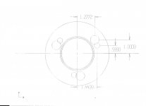
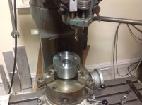
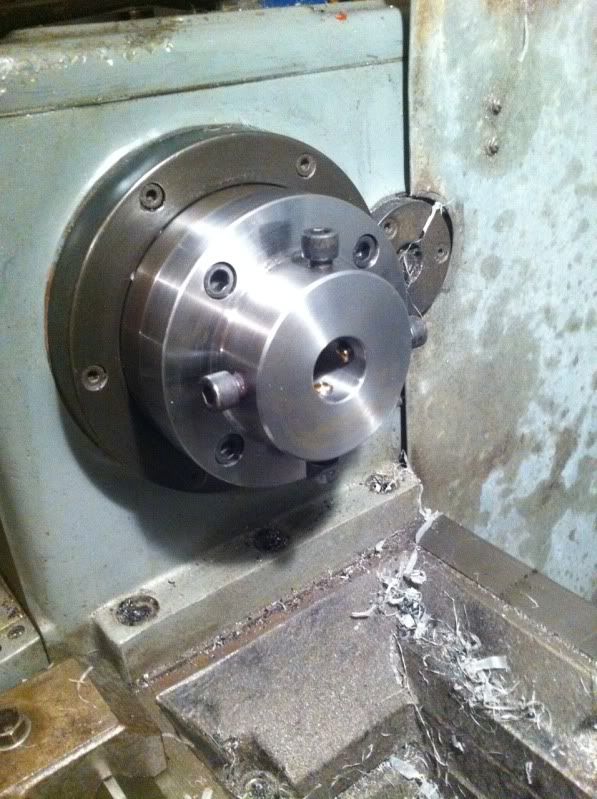
I am trying to make a back plate for a D1-4 chuck. BUT I am finding it difficult to determine correct location for the locking screw holes. I am using a super spacer to hold my work piece on a mill. Cutting the holes and threading for the pins is a cinch but the locking screws' location is not so simple. All the drawings I have found describe the locking screw holes' location in a way that is difficult for me to understand how to machine it. I think I understand why the drawings are written so but still it is a difficult situation. Please help.

Tom Darragh
 
Last edited:
Hi Bill.
Thank you for your very quick response.
You are saying that precision is not important here. I understand that. My question was not "why" in all this. I just would like to know an angle or amount of degrees to turn my super spacer to, to get at least in location so that I am not so far out of whack to cause problems. Part is mounted on mill now and if someone knows the amount of degrees to turn the part and the distance from center I would be very happy. The pins are located 1.625" from center and the locking screws are a short distance less. How much is what I would like to know.
 
I would think that you could adjust the camlock pins to the right depth to fully engage them and then lock in place on the lathe. Unlock with chuck wrench and carefully remove your plate. Mark where the locking pins need to go and just drill and tap.
As was mentioned, the locking pins are not crucial as far as accuracy is concerned and you should be able to get what you need from mocking it up on the spindle.;)
 
Simple trig problem

1.625 X cos of 15.6 degrees gives a value of 1.565 for a radius, and the drawing plainly states that is the degrees of rotation off the hole position
 

Attachments

  • D4 Chuckscrop.jpg
    D4 Chuckscrop.jpg
    38.9 KB · Views: 3,591
I made one of these for my heavy 10. I located the holes for the studs and locking screws on my coordinate measuring machine. When it really comes down to it, the locking screws are not necessary. You can omit them if you assemble the studs in their threaded holes, mount it on the spindle and operate the locks. You can determine the proper rotational position of the studs by where they lock up properly. When you have determined where they belong, just use some lock tite to hold them in their proper rotational position.
 
D1-4 help

Simple trig problem

1.625 X cos of 15.6 degrees gives a value of 1.565 for a radius, and the drawing plainly states that is the degrees of rotation off the hole position

Thanks John BUT I did not take even algebra in high school. I am now 62 and about 20 years ago I took an algebra class. I got a B. It was very basic algebra. Never took trig. Maybe some time I will take a trig class but probably not. Thanks very much for your help but still pretty lost in the math department.

I am hoping that someone has the simple distances already figured out and will tell me. The work piece is still on the mill and I don't want to take it off till I can somehow reasonably locate these pesky holes. I will try to post a picture of my setup.

Thanks again.
 

Attachments

  • image.jpg
    image.jpg
    87.3 KB · Views: 1,076
Not to put too fine a point on it, but when setting up D1-anything for best and proper camlock action, the locking pins are not even in-place. They are inserted AFTER the best fit has been determined - so the exercise need not be repeated every time a hunk of nose-art is changed. Note the 'several' degrees of freedom they support.

Hardly Rocket Science to make a drill jig that serves to locate both the pins and their locking screws.

Generally far better use of time and funds to simply purchase new or used backplates, as the taper relationship and the pin profiles are both far more work to get 'right' than the silly little lockscrews.

Further, the cost of proper alloy, machined/ground to be precisely on-size and profile, and properly heat-treated for the pins, loose, is usually more than the cost of a backplate, complete WITH pins and lockscrews.

Good ones do tend to last for scores of years anyway, so the annual cost is barely a rounding-error in the average shop.

D1 ADAPTOR might be a must-make item. D1 art to fit it thereafter it is wiser to JF buy.

Bill


Hello Bill,

I am very novice at this machining business. I need a special type of chuck for working on gun barrels. Making this not only gives me a nice custom chuck but also the experience of making something somewhat precise. I am having fun doing this but I have found part of this project to be a little over my head. Thanks very much for your kind assistance.
 
Simple trig problem

1.625 X cos of 15.6 degrees gives a value of 1.565 for a radius, and the drawing plainly states that is the degrees of rotation off the hole position


Ok. John. I think I got it. The axis of rotation is off the center of the hole and is parallel to the line that rotates off the center of the part. Duh! So 15* - 36' (15.6*) is what I need to dial into my rotary device. And your trig solved the distance from center. Yea! Thanks!
 
You'll really want to NAIL the mating angle between your plate and the spindle nose. A tenth's indicator referencing the spindle nose, and mounted to your compound, until it reads no deflection as you crank the compound in/out, will get you there IF your compound cuts straight. Then you leave the compound set to that angle, and as long as you have the swing on your lathe, cut the angle on the part.

I don't think there's another way to make a one-off that will be anywhere near precise enough. OTOH if you are making a spider chuck like this one:

3FA31D6F-0EC1-4AF7-A049-B40724DF49A1-217-000000B5AB253329.jpg


..... then really, it's a 4-jaw, and works independently of mounting precision, more or less. But you don't want to mar your spindle nose with a funky angle, either.
 
The basics are not as complicated as they are 'sold' to be by the student loan racketeers. Don't take THEIR courses. Not first, anyway.

Sohcahtoa: Sine, Cosine, Tangent

Easy-peasy to do the math in one direction.


The thick books of eye-blurring tables existed because electronic calculators that could do the math in the OTHER direction did NOT exist.

Now they do, so it is but a few keystrokes. And knowing what to ASK the calculator, and what to do with its results. Of course.

Don't let it intimidate you. As at the time you learned to walk without falling down, put food into your mouth, not ear, you had begun to master four-dimensional (time and latency) spherical trig and solid geometry under the distortion of a one-gee gravitational field moving at a high rate of knots.

Costs a Hell of lot of money to create a machine that can do what a human child can do, and I ga-ron tee the creators don't enjoy the near-misses and failures nearly as much, let alone the successes.

;)

Bill


Hi Bill,

Thanks again for your help. I am not avoiding trig. I enjoyed the problem solving tricks of algebra. Machining is full of trig. And it seems simple trig will solve most machining problems. I enjoy learning math. Just not going to take time to take a class. Just gonna learn as I go. As problems come up I get more and more understanding. Still not quite there yet but soon I hope. Nomenclature is big issue now: cos, tangent, etc. are clearer than ever but still need to focus more. Thanks for the encouragement.

Btw: I am not going to MAKE barrels just do some simple work on them. Most barrel work can be done with simple addition and subtraction. I can handle that. Even the actions can be trued with simple math BUT with some keen machining skills. Actually I am pretty excited to see that I can now machine some things with a fair amount of precision that not too long ago gave me a heck of a time. This chuck for instance. I am pretty sure that it will fit pretty good on my spindle. Even if it does not, it will be ok because the chuck doesn't need to be real precise. But I worked hard on it so as to practice accurate machining.

Sohcahtoa: seems to be an Awesome source for the basics. Thanks again!

Tom D.
 
You'll really want to NAIL the mating angle between your plate and the spindle nose. A tenth's indicator referencing the spindle nose, and mounted to your compound, until it reads no deflection as you crank the compound in/out, will get you there IF your compound cuts straight. Then you leave the compound set to that angle, and as long as you have the swing on your lathe, cut the angle on the part.

I don't think there's another way to make a one-off that will be anywhere near precise enough. OTOH if you are making a spider chuck like this one:

3FA31D6F-0EC1-4AF7-A049-B40724DF49A1-217-000000B5AB253329.jpg


..... then really, it's a 4-jaw, and works independently of mounting precision, more or less. But you don't want to mar your spindle nose with a funky angle, either.


Hi Long Tom,

Yes, my (spider) chuck is similar. Seems your spindle is a "screw on" type.

I think my angle is good. I used Prussian blue to test for fit and it seemed ok. I left part in chuck and removed from spindle and placed part on spindle for fit. At first the only problem was that the face of new chuck (part) did not have correct gap between it and face of spindle. I needed to face a few thousands off to get proper fit. I think I am there.

Now that I have the pin holes drilled and tapped, next to drill and tap locking screw holes (thanks to Mr. Oder, I have the correct locations) and then the true test...put on lathe and "cinch it up." Then, if all is well, I will place on super spacer again and drill 4 holes for holding screws for the gun barrel. And if it works as planned, I will be a "happy camper."

OTOH?
 
Ummm..... Might want to stick to muzzle-loaders or blowback self-loaders for a while, then while you get your arms around it all.

The geometry of turnbolts and their various schemes of camming, locking, and cocking - ditto Browning or Petter recoil operated mechanism profiles are a tad less forgiving than D1 hardware is.

:)

Bill

Hi Bill,

Gonna stick with Remington 700s for now. I have mentors. And some of the design is fairly complicated but I am going very slow (taking my time) and my understanding is growing. Someday I will fully build my own custom rifle. Getting closer and closer every day.

Tom D.
 
Hi Long Tom,

Yes, my (spider) chuck is similar. Seems your spindle is a "screw on" type.

I think my angle is good. I used Prussian blue to test for fit and it seemed ok. I left part in chuck and removed from spindle and placed part on spindle for fit. At first the only problem was that the face of new chuck (part) did not have correct gap between it and face of spindle. I needed to face a few thousands off to get proper fit. I think I am there.

Now that I have the pin holes drilled and tapped, next to drill and tap locking screw holes (thanks to Mr. Oder, I have the correct locations) and then the true test...put on lathe and "cinch it up." Then, if all is well, I will place on super spacer again and drill 4 holes for holding screws for the gun barrel. And if it works as planned, I will be a "happy camper."

OTOH?

Howdy back!

That's my lathe, which is an A1-6 spindle nose. I *think* the basic geometry of the nose is the same as the corresponding D-series nose, except I'm bolting it on and you are camming it on. IDK what's "best".

I made that chuck for chambering rifle barrels but have gotten utterly swamped, and so it's all on hold for the moment. I have a couple actions (Rem 700) and a couple barrels (Pac-Nor) all set to go... But my lathe keeps humming along making money, and I'm building a house. Anyway-- seems like you have the drive and humility to get where you want to get.

Making your own foundational tooling is a very legit path.
 
See drawing. Dimensions are a little hard to read. The X positive dimensions are 1.2772 and 1.4439. The Y positive dimensions are 1.0003 and .5990. These are distances from the center of the spindle nose. After indexing 120 degrees, repeat holes until done. Dimensions were from a coordinate measuring machine off a existing workpeice.
 

Attachments

  • spindle nose.jpg
    spindle nose.jpg
    80.3 KB · Views: 2,945


Back
Top