What's new
What's new

Holding odd part in lathe

rwskinner

Aluminum
Joined
Sep 22, 2015
Location
Somewhere in Texas
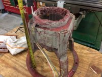
I need some advice on making a fixture to hold a part in the lathe so I can do some light machining on one end. Here are the details...

I have 19x80 Leblond and need to machine a feature on one end of a generator stator. The stator housing is about 10" long and has windings sticking out about 1.5" on each end. It's close to 8" OD but I can not chuck up on the O.D. of the part due to the windings sticking out each end, not allowing it to get close enough to the jaws.

The stator does have a nice bore that measures very uniform and is close to 6" ID.

I have a big chunk of heavy wall 4130 (6.250 OD x 3.750 ID) and I was thinking about machining a one ended tapered mandrel of sorts.

My thinking is, if I put a light taper on the mandrel, I could lightly press it into the stator. The length inside the stator is close to 6".

The overhang doesn't bother me that much as I have fairly light cuts to make, however there is no way to secure the stator to the mandrel other than the taper friction fit.

Does this have merit? What would be a good taper to shoot for that would be self centering and wedge well enough to secure the part?

No room for a tailstock center and can't use a steady rest.
 
What sort of "light machining" did you have in mind? A picture is worth a thousand words ... or 126 in this case. That concept you described sounded sketchy as hell, even by my sketchy setup standards! ... like we're talking "ya gotta be kidding" kinda sketchy!!!

As much as I'm a lathe guy, from what you've just said I'd be fixturing that sucker up in the mill and using a boring head. Fix it to an angle plate using the motor mounts and go nuts. Don't get hit in the head with a flying electric motor. Live to post another day on PM. Basic kinda stuff like that.
 
Most of the weight is back towards the chuck. I turn the DC housings all the time with 16" overhang. Boring and sleeving bearing bore. The DC housings have a nice thick, round OD I can clamp to.

This is an AC housing, not very many good ways to hold on to it.
See below.

IMG_0698.jpgIMG_0701.jpgPart.jpgStator View Inside.jpg
 
I'd be cautious about pressing anything into the stator. The laminations tend to flex in the direction of insertion so pushing in the opposite direction is likely to cause them to dig in to the mandrel and make removal pressure very high, and could damage something. Same issue as removing a shaft from a rotor: it has to be pushed in the proper direction (mind you a rotor's shaft is not tapered).

I'm thinking you should use some kind of expansion mandrel instead: make your mandrel a close slide fit, and machine a groove on each end to hold a 1/4" cross section O-ring. The groove should be open on the end, so that you can bolt an endcap over the O ring and compress it, forcing it to expand inside the stator.

I also think you should have a shaft through your mandrel to reach the tailstock in order to stabilize the thing. If you are machining that skinny ring, it's going to need additional support to stop it from ringing and you can add such additional support to the mandrel shaft.
 
Pete's correct - it is mill & boring/surfacing head work. One or the other of my Chandler-Duplex could actually earn a crust.

However... let us presume you HAVE NO suitable mill OR boring AND 'surfacing' head.

"Light machining" on something that b****y awkward is sometimes best done with HAND TOOLS.

I'd be using the Leblond to make meself jigs, fixtures, or stock-metrology-holding gage frames so I could be assured work done by hand was flat, level, concentric, whatever, whatever, whatever, wha... - was important to the part fitting and working as required.

'Hand' including powered hand tools, of course. An 'oscillating' tool can be used much as a scraper can be. I "know" hand files - practically in the 'Biblical Sense', I am that old - but am in no hurry to go back to them if a mounted disk or stone or carbide-grit oscillating saw-blade under power will give me the lighter touch and less muscle fatigue.

IOW - to me.. "light" machining makes this a measuring exercise more than a workholding exercise.

And you have to measure for success anyway, so...
 
I would make the mandrel a close fit with no taper. Then I would make a spider or a single cross bar, goes between the winding and rests on the metal. make a slightly longer one for the chuck end that rests on the mandrel with some blocks or weld it inside the mandrel. Drill a 1/2" hole in the center of both, lastly a piece of allthread to replace the rotor to clamp it down.
This should work at low speed but if it slips it may cut the windings.
I think we need to know what and were you need to machine to come up with better ideas.
Bill D.
 
I have used 5c ID collets up to 6 inch dia to hold parts like that. Might be a little costly for only one part ,but the collets can be turned and reused many times. You can look up Rovi collets they are in the Los Angeles area and make a good product. jimsehr
 
Bolt some big pieces of flat bar or angle to the four bosses, weld them to a ring to create something similar to what is on the other end, just shorter. Chuck the other end and indicate the work round on both ends. Face off the end of the welded fixture so it is square. Turn at least a shoulder on it so you have something to indicate from. Flip it, indicate both ends again and do whatever work you have. You may need a custom built pipe center or plate with a very shallow lip to run a center in the outboard end. Might be a chatter monster and try to jump out of the chuck on you, otherwise.
 
Maybe I'm missing something, but can you bolt the circular base it's sitting on to a faceplate, and shim until whatever surface you wish to machine is in alignment? If you need to bore the hole in pic 3, that should be reachable and reasonable with light cuts. If you need to face that side of it, more of the same. If you need to face the opposite side, stick a boring bar thru the hole with the cutter re-oriented.
Chip

If you need to machine some other surface that what I guessed, then, well, never mind. Nothing to see here.
 
I really don't care for the lathe idea either however these are normally done in the lathe. I haven't seen the fixture, but I believe its a slight slip fit and then gets tack welded to the fixture, machined, then cut off.


If you look at picture 4, you see a cross and round hole. On the back side of that is a bearing cup that has to be bored, sleeved, the finish bored. That's why you really can't put a center or arbor all the way thru it.

In my mill, it's a very very tight fit, as I only have 16" of Z on my 10x52 Sharp TMVK.. I would prefer to do it in the mill as well, and I've been making a fixture this morning to hold it up off the mill's table slightly so the windings are barely above the table. Then see if I can get a boring head stuffed in there.

When sitting on the mill table, the small square end is down, and the large ring is pointed up.


Most of the weight is back towards the chuck. I turn the DC housings all the time with 16" overhang. Boring and sleeving bearing bore. The DC housings have a nice thick, round OD I can clamp to.

This is an AC housing, not very many good ways to hold on to it.
See below.

View attachment 194015View attachment 194016View attachment 194017View attachment 194018
 
Personally I'd do something off the c-channels to a faceplate maybe. I'd avoid contacting the inner stator surface at all costs because I'd assume that it is easily damaged rendering the whole thing useless.
 
I think where you're headed on the mill is the way to go. Keep it low, and know you may have to mount your tooling while reaching thru the ring structure, but it should be much safer than a lathe lash-up. Good luck, and post pics.

Chip
 
I really don't care for the lathe idea either however these are normally done in the lathe. I haven't seen the fixture, but I believe its a slight slip fit and then gets tack welded to the fixture, machined, then cut off.


If you look at picture 4, you see a cross and round hole. On the back side of that is a bearing cup that has to be bored, sleeved, the finish bored. That's why you really can't put a center or arbor all the way thru it.
.

Make a plug that is a hand press fit with the winding side & center drill it.
Make another plug that is a snug fit with bearing bore, hold this in the lathe chuck.

Place the part between the two plugs, use the tailstock to support the large plug, chuck holds the small one.

This will get the part centered with the lathe spindle axis.

Remove lathe compound, block and shim the part to the lathe carriage/cross slide. Bolt it down.

Now you are set up to bore using a boring head in the headstock.
 
Make a ring from heavy wall tube that sits on the face where the windings stick out, be sure it sticks out past the windings,
drill it to match the four holes in the housing, bolt them together and grab the whole assembly in a 4-jaw chuck. Should be
easy to dial in from there and it would be a solid and safe setup.

Looking at the pics you might even get away with taking a piece of pipe or tube and tacking it to the outside of the four channels
in the frame--easy to work with a 4-jaw from there...
 
In my mill, it's a very very tight fit, as I only have 16" of Z on my 10x52 Sharp TMVK.. I would prefer to do it in the mill as well, and I've been making a fixture this morning to hold it up off the mill's table slightly so the windings are barely above the table. Then see if I can get a boring head stuffed in there.

When sitting on the mill table, the small square end is down, and the large ring is pointed up.

A tight fit is still a fit :) I think your insurance company will be pleased you're not going to swing it based on the the setup you originally described.

If I HAD to do it in the lathe I think I'd rip the compound off and make up a fixture so I could line bore it. In fact the only reason I wouldn't do it that way is because it would mean making up a fixture, but since you're doing that anyway ...
 
The job is already done. This morning after I asked the question, I had already started making a fixture for the mill. I had to stick it over to one end of the table but I got her done.

IMG_0722.JPGIMG_0717.jpgIMG_0721.jpg

You probably don't want to see how the DC housings are done then.....
Here are a few of the DC housing we do all the time.
IMG_0663.jpgIMG_0664.jpg


A tight fit is still a fit :) I think your insurance company will be pleased you're not going to swing it based on the the setup you originally described.

If I HAD to do it in the lathe I think I'd rip the compound off and make up a fixture so I could line bore it. In fact the only reason I wouldn't do it that way is because it would mean making up a fixture, but since you're doing that anyway ...
 
You probably don't want to see how the DC housings are done then.....
Here are a few of the DC housing we do all the time.
View attachment 194076View attachment 194077

You're right. I wouldn't want to see that ;) Not quite as sketchy as you were proposing initially, but still dodgy in my opinion, and all good until one day the tool chips or something, digs in and there's a mighty crash. I pulled a job from a chuck a few months back, I can't even recall the details now, but i hadn't done it for years and it was a good reminder to respect stick out!

If this is something you're doing "all the time" I would have expected you to come up with a better solution than that to be honest. You have the possibility to run soft jaws, T-slots in the chuck, etc. I see all manner of fixturing methods even at casual glance.

Look up "Normalization of deviance" as to why I say that.
 
Those stator laminations are all insulated from each other. If you had pressed something into them, there's a fair chance you'd smear them together enough to un-insulate them.
 
From the factory, they are all stacked in a jig, pressed together, and have weld beads down all 4 sides. I have the original MFG drawings for them and it shows the build process. I don't think the weld bead makes for a good insulator :)

My fixture I made this morning was a snug, slip fit, then a bolt thru the center going into a T-Slot keeping it pulled down. I had no issues with chatter or keeping it centered and all went well. I use the cast iron EZ-Sleeves just because they cut so easy. Much better then the 1021 DOM tubing I used to use for sleeves. I still use DOM tubing if I don't have a sleeve in stock but pulling a sleeve off the shelf, liquid freezing then sliding it in is way too easy than to have to stop and make one.


Those stator laminations are all insulated from each other. If you had pressed something into them, there's a fair chance you'd smear them together enough to un-insulate them.
 
I do a couple a month. Yes, you are right, that 3/4" of depth on the jaws is scary. The soft jaws would be problematic since the round housing that I have chucked up is made from a rolled plate, 3/4" thick and is far from round, and vary lots from housing to housing. Then there is a big dobber weld at the joint down one side. It's a bit painful to indicate some of these in, especially if the frame is bent from some yahoo removing it with a sledge hammer or pry bars instead of a puller.

I have to admit, I have always been weak on dreaming up fixtures. I welcome all ideas, I'm not too proud to ask for help.

I had thought about a round plate with 4 holes in it, then a large center hole. It would slide over that bearing cup, and 4 all-threads would go into t-nuts in the chuck. I figured if anything, it would help avoid it being thrown out. The issue I believe, it would make dialing it in pretty hard if I kept it pulled against the chuck very tight, again, nothing is flat or square on these. I may try that and just snug them slightly for insurance?

You're right. I wouldn't want to see that ;) Not quite as sketchy as you were proposing initially, but still dodgy in my opinion, and all good until one day the tool chips or something, digs in and there's a mighty crash. I pulled a job from a chuck a few months back, I can't even recall the details now, but i hadn't done it for years and it was a good reminder to respect stick out!

If this is something you're doing "all the time" I would have expected you to come up with a better solution than that to be honest. You have the possibility to run soft jaws, T-slots in the chuck, etc. I see all manner of fixturing methods even at casual glance.

Look up "Normalization of deviance" as to why I say that.


Back
Top