What's new
What's new

How to wire start/stop to main contactor ??

dazz

Stainless
Joined
Aug 20, 2006
Location
New Zealand
Hello

One way to connect the start/stop control switches is shown in the picture.
The switches will open/close the main supply contactor for a machine tool. In this case, a lathe.
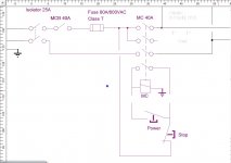
start stop Circuit.jpg

The problem with this is that it takes line voltage out to the on/off switches.
I'd like to keep all line voltage within the electrical controls enclosure and have only 24V going out to the switches.

There are a few constraints:
The contactor has line voltage coils and that won't change.
I want all power to be drawn through the contactor, so having a separate always-on 24V supply before the contactor is at least undesirable.

If I have to use the circuit in the picture, I will armour the on/off switch cables.

Any suggestions?
 
you can use the same basic circuit, get a 24v coil for your motor starter, and a small transformer to supply your 24v, unless you have 24v somewhere else. I would also incorporate the overloads into the circuit, possibly before the e stop or stop button, so if your contactor kicks out due to an overload, it won't restart unless someone pushed the start button again. Just for safety's sake. Now, where your control circuit wires goes to the line, just run them to the 24v supply.
 
The schematic you link is the time proven, industry standard for 3 wire start/stop control. 120 volts at the operator station is generally considered to be non lethal. If you want all power to be "drawn through" the contactor then there will be no control power available when the contactor is open..it won't work.

The only way to get low voltage control is with a low voltage coil for the contactor and the appropriate transformer to power it. This is simple and done all the time.

It sounds like you are worried about damage to the wiring to the control station. Sealtite flexible conduit or BX (armor) or rigid conduit or even EMT would protect the wires from anything other than a well placed IED or a direct hit from a Sherman tank.

It sounds like your lathe is powered by 120 volts. Look at a garbage disposal 'air switch'...maybe something like that would work to switch power to your contactor. You may be trying to over-think this thing.;)

Stuart
 
If you are worried about high voltage run the hot side to the coils and use the neutral side to control.

You will have 120 vac present on an open switch but that is due to no current through the circuit.

To make it more safe add a gfi outlet as a service outlet and use gfi power for your controls.
 
Hello

We have 220VAC here so it is potentially lethal.
I have used this circuit on another lathe but the controls were accessible on the enclosure.
With this latest lathe, the on/off buttons are remote from the controls enclosure.

I am not really enthusiastic about having an always-on 24V supply so I think my best option will be to armour the cables to the on/off switches.
Not shown (yet) in the circuit diagram is that the VSD has a fault output. This will be wired to trip the contactor.
The e-stop is electronic. Fully controlled by the VSD. The e-stop will not be wired to the contactor.
 
There are a couple ways to approach this.

1. add control transformer and ice cube relay that "bridges" between 110vac (or 24vac) and 240vac.

2. add control transformer and change contactor to one with 110vac coil voltage

You mention a VFD...if so it already has its own low voltage power supply sufficient to supply the switches that go back to inputs on the VFD itself.

Only good reason for 110vac then is for a worklight.
 
Dazz,

You mention a VSD..is that like a VFD, a variable frequency drive? If your lathe is powered by a variable frequency drive the whole scenario you laid out in the first post makes no sense.


Are you powering your lathe with a Variable Frequency Drive?


Stuart
 
I do not understand your hesitation in having a 24 V transformer connected to the line "at all times". Such a transformer, if there is no load on it, will draw very little current so there is almost no cost associated with leaving it on. The only time it will actually draw significant current is when it is powering the 24 V relay that controls the contactor.

You can connect it to the mains past the main power switch (or breaker) so that main power switch can turn off all power to the machine, including the transformer. Any such machine control circuit should have a main power switch for safety anyway. This is how many, many control circuits are done. Just flip that main power switch off when the machine is not in use.

This arrangement is standard practice and well proven in actual use.
 
A VFD is what you speak of as a VSD, should be after the contactor. Those devices often have all sorts of overloads, high voltage low voltage, frequency, temperature alarms, shut downs.

If used in a lathe type application, the VFD should be your motor control, not the contactor. A vfd is not supposed to be started under load, damage almost a sure thing if you do. The keypad or remote switches are what should be used to control the lathe motor.

A few years I had a short in the braking diode of my Vfd, it melted the ceramic braking resistor. After that I installed a contactor before the VFD. Using a push/pull knob turns the contactor on and powers the VFD. Then all controls are with the remote wiring, the lathe is powered all day then I turn it off at night.

You need to rethink your plan, using the requirements of the VFD, The lathe, and electricial code.
 
Hello

Thanks for your comments.
Let me provide some additional info for clarification.
I am an Electronics Engineer and also registered to do electrical installation work.
I haven't shown the full circuit diagram but the main contactor is ahead of the VSD.

I am aware that there are a number of experts on machine tool controls on this forum so I was hoping to tap into that expertise to seek out current best practice. The circuit I have used is a traditional one but not necessarily the best one.

I aim to use the contactor as a second isolator. For safety reasons, I would rather not have an always-on 24VDC supply because that will require an always on 240VAC supply not controlled by the contactor. I know of at least one accident where supposedly dead equipment still had a live auxiliary supply.

My VSD manual specifies a limit on the number of starts/30 minutes. Under normal operation, I would expect to close the contactor in the morning and open it at the end of the day.

Your point about melting the braking resistor is relevant. I haven't yet decided how to address this problem. I can either measure the surface temp of the resistor and and trip the main contactor on over temperature (a fault), or I am considering putting a contactor with a motor overload relay in series with the braking resistor. Excess load would open the resistor circuit and optionally open the main contactor. I know the load rating of the resistor but I don't know how this translates to surface temperature. I don't have a power supply big enough to fully load and test the resistor.
 
Huh!

Dazz, you are concerned that somehow, the 24V wiring for the contactor coil will fail, ON! Then somehow the control wiring for the vfd will also fail ON.

This may be a silly question, but do you hit the main breaker AND pull the meter when you leave the house. Thats the failure you are considering. In that case there are other problems.

Read the setup of the VFD, lots of information there.

Hello

I am not concerned about having 24VDC always-on. The problem I see is that 24VDC power supply must be fed by 220VAC whether the main breaker is open or closed. Some (if not most) maintenance staff will make the assumption that the plant is dead if the main breaker is open.

To use your household analogy, if you open the wall switch to your electric range, you would probably expect to be able to stick your hand into the wiring without getting zapped by some auxiliary supply.

Of course you would say that you would check with a voltmeter before doing that. I have stopped an electrician as he was about to touch live 400VAC terminals because he "thought" they were dead. One of my staff got hit with 110VAC when he leaned on terminals in a "dead" 440VAC switchboard. He had to be pulled off the terminals.

A common standard for isolation is to have two barriers between the hazard and a person. If staff are relying on an isolation switch plus the breaker, then having an always-on 220VAC fed 24VDC supply violates this standard.

I'm not understanding what you are doing obviously. On any piece of industrial equipment there should be a main MANUAL disconnect to the machine that is lockable in the OFF state. This will remove ALL power to the machine after the switch. This is the lock-out point for maintenance and should be identified as such. With that lockable MANUAL main switch ON, 24v can be supplied to the equipment in a safe manner.

You should never have a contactor supplying main power to a machine from the supply without a manual switch ahead of it on the supply side. (The dots are just to keep the spacing)

...................................................................------->Main Power for machine
..................................................................|
LINE---->MANUAL LOCK-OUT SWITCH-|
..................................................................|
..................................................................------->24V PS --->control wiring
 
A Cabinet fed with more than one source of power can be dealt with in several ways. A micro-switch on the cabinet door that kills power to a transformer or contactor is one way. Calling attention to the remote source of power in the cabinet is another way. Voltage Warning Labels - Caution This Equipment Is Supplied I have used both of these methods.

I think I would pass your job off to a qualified industrial electrician...save all your high priced talent for designing space shuttles and laser beams.:o

Stuart


Back
Top