deltaenterprizes
Stainless
- Joined
- May 9, 2006
- Location
- Longview,TX
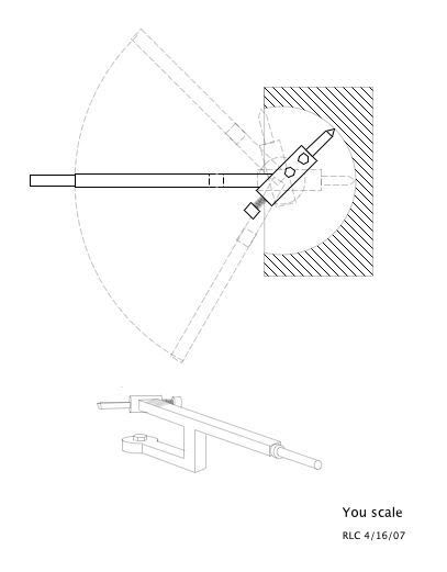
How would you cut a hemisphere on a manual mill or lathe?
Follow along with the video below to see how to install our site as a web app on your home screen.
Note: This feature may not be available in some browsers.


")
Notice
This website or its third-party tools process personal data (e.g. browsing data or IP addresses) and use cookies or other identifiers, which are necessary for its functioning and required to achieve the purposes illustrated in the cookie policy. To learn more, please refer to the cookie policy. In case of sale of your personal information, you may opt out by sending us an email via our Contact Us page. To find out more about the categories of personal information collected and the purposes for which such information will be used, please refer to our privacy policy. You accept the use of cookies or other identifiers by closing or dismissing this notice, by scrolling this page, by clicking a link or button or by continuing to browse otherwise.