What's new
What's new

Magnetic bend brake (e.g. MagnaBend)

Bob Engelhardt

Plastic
Joined
Jan 13, 2011
Location
Massachusetts, USA
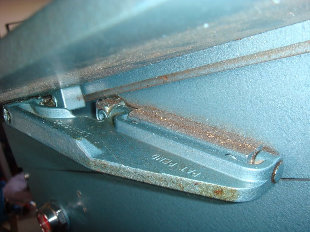
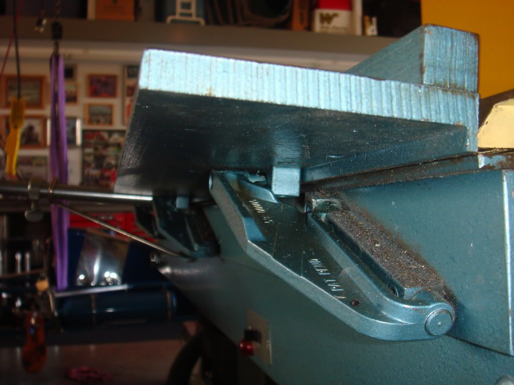
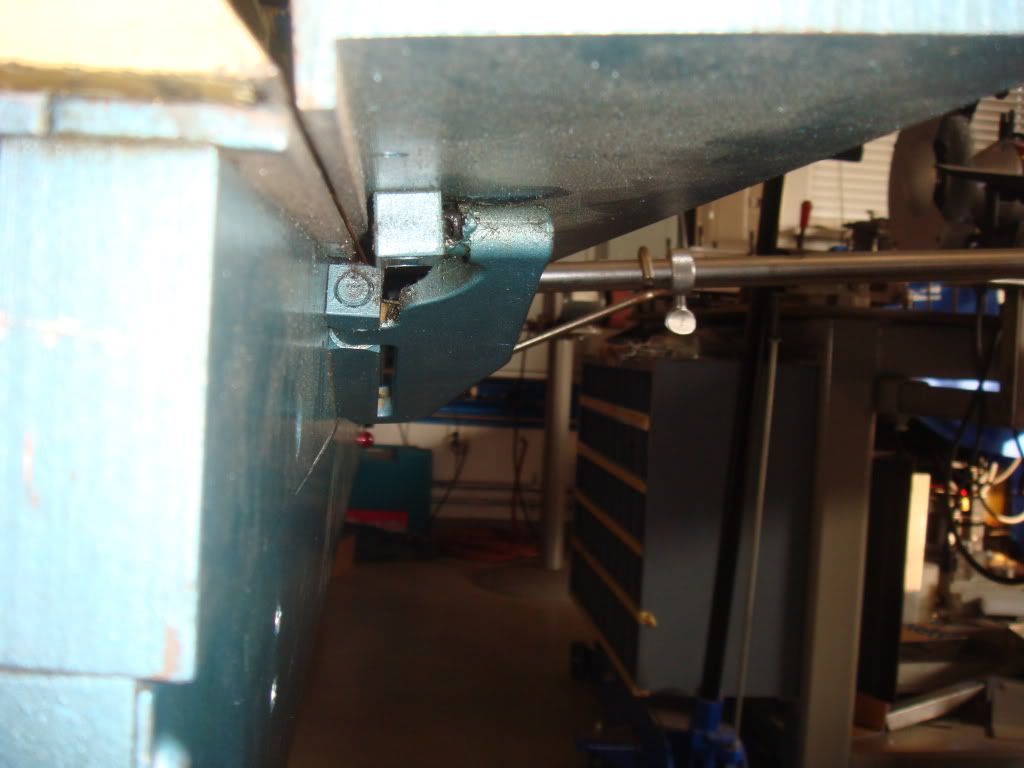
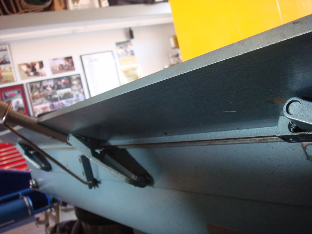
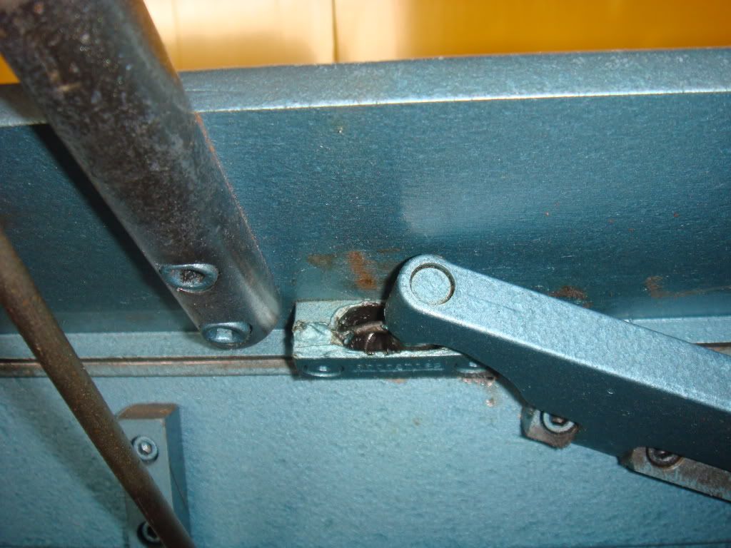
A previous thread addressing this ("Need some technical advice regarding electromagnets..") was closed due to the meaningless topic title. I hope that this thread can continue it, in particular I hope that member 307startup can give us some info on how those mysterious hinges work.

Or from member Mark Leigh who posted that he has one of these brakes and would be willing to post pix of the hinges.

Bob
 
Milacron - could you edit your closing post on the "Need some technical advice regarding electromagnets.." thread to point to this thread as the new location of the discussion?

Thanks,
Bob

BTW - I tried to request this via direct mail to you, but got "Milacron has exceeded their stored private messages quota ..."
 
Hey Bob...

Thanks for bringing this topic back up.

The hinges are pretty simple once you realize that they work on 3 pivot points...as they fold up, they also rotate...this allows for the thru-clamping that makes this style brake very useful for certain things (and people like me).

If you watch the videos on YouTube closely, you can see how they articulate.
 
you know Gavin, I have seen these advertised but never really gave them much thought. I am not a sheet metal guy anyway, but that is pretty darn neat. Without dragging this thread on too much do you have anything interesting to share about your involvement?

Charles
 
Hinge photos

DSC01794.jpg


DSC01795.jpg


DSC01796.jpg


DSC01792.jpg


DSC01793.jpg


Let me know if you need more views
 
I did not have any thing to do with the Magnabend, but I am friends, and work with the inventor (Alan) and the hinge inventor (Geoff). I hope that Alan will one day write a history of the Magnabends development. The original prototype without the current hinges is still bolted to Alans bench; the current hinges are a very important feature of the machine. It is an special feature of the Magnabend that the ends are open so you have much more versatility in where you can out put a fold than with a standard pan brake.
 
Presumably the point of the hinges is that you can have the ends open. But just as important, you aren't limited to just a hinge at each end, so should be able to make things stiffer.

Interesting mechanism!
 
I read the patent but didn't understand it. I wonder if the examiner at the patent office understood it. I'm in awe of the inventor. Tip: if you haven't read it and intend to, skip the first part of the "Description" & go down to "5". The first part is completely unintelligible!

In Mark's pictures, it looks like the "spherical internal hinge" is used, but the hinge in the video looks different, 'though it's too fuzzy to be sure which form.

Anyhow, I don't have anywhere near the skill needed to make these. But I am considering making a brake with the magnetic clamp. To me that is the biggest advantage that the MagnaBend has. The hinges just allow for bending at the ends & I don't really need that.

Bob
 
Here's the patent for the brake itself, it's patent 4111027:
Electromagnetic apparatus - Google Patent Search

It's quite straight-forward and has non-protuding hinges that are basically pin hinges sliced in half, axially. I've heard that it's because these were lacking that the new hinge design was commissioned.

But I don't see what the problem was with the original hinges. Other than that when the bar is rotated there are areas of the bed and the bend bar that are open. This would leave the material unsupported in those spots and distortion might occur.

Can anybody see anything else? Currawong - do you know what the problem was?

I've copied the hinge figure from the patent:
MagnaBendHinge.jpg


Bob
 
I have spoken to Alan about the hinges and he has brought a box of the prototype hinges into work today. I think he will write a bit of a story about the Magnabend development over the next week or so. Geoff is away on holiday at the moment (far southwest of Tasmania) where there is no technology, but when he gets back I will see if he want to add something.
 
I have spoken to Alan about the hinges and he has brought a box of the prototype hinges into work today. I think he will write a bit of a story about the Magnabend development over the next week or so. Geoff is away on holiday at the moment (far southwest of Tasmania) where there is no technology, but when he gets back I will see if he want to add something.

Hi Bob,
I am the inventor of the Magnabend sheet metal folder and Gavin has encouraged me to respond to this forum and to write a bit of a history of the Magnabend.
This is now in progress and will be published on my website: Alan Bottomley's Web Site.
Meanwhile, to answer your questions re the hinge:
The original "cup hinge" worked ok for moderate angles of rotation but was not satisfactory for angles much beyond 90 degrees. (There was not a problem regarding lack of support for the workpiece).
If you want to build your own machine I could possibly give you a few pointers. What length of folder are you wanting to build?
Alan.

Alan...

What was the issue exactly with the original cup hinges past 90* of rotation?

Though I'm not Bob, it was my original thread about building my own "MagnaBend" that prompted this thread.

I would love any assistance you may be able to provide regarding the mechanics of the unit, as well as Bob would, I'm sure.

Hi 307startup,
The main issue with the cup hinges was to do with lack of engagement at high angles. When you started to return the bending beam the hinges would jam up; a bit like a drawer if you try to push it back in by pushing on one side instead of in the middle.
Cheers, Alan.
 
Alan...

What was the issue exactly with the original cup hinges past 90* of rotation?

Though I'm not Bob, it was my original thread about building my own "MagnaBend" that prompted this thread.

I would love any assistance you may be able to provide regarding the mechanics of the unit, as well as Bob would, I'm sure.

Hi to Bob and 307startup,
If you want to make your own Magnabend then the single most important bit of information that I could give you is the gauge of wire to use for the electromagnet coil.
This is contingent on the length of the machine and on the supply voltage which is to be used.
If the wire is too thin then you will not get enough ampere-turns and if it is too thick then the power dissipation will be too high. The gauge is surprisingly critical.
Also, contrary to popular belief, you cannot increase ampere-turns just by putting in more turns. Assuming that the coil will be supplied with a constant DC voltage (rectified AC typically) then if you, say, double the number of turns then the coil resistance will be doubled (actually a bit more than doubled because outside turns are longer) and thus the current will be halved and the net result is no increase in ampere-turns!
Extra turns do however reduce the overall power dissipation.
Cheers, Alan.

Ok...for example? How about for a 48", 72" and 96" brake? 110/120VAC or 220/240VAC to 12VDC or 110/120VDC magnets...
 
Alan, Thanks for joining us. I'm a great fan of the MagnaBend - it's such a cool idea! I can't believe that it was patented in 1980, yet I'd never heard of it until a couple of weeks ago. My reaction then was: "I wanna' build one of those". That was before I appreciated how complicated the hinges are.

But, I've been thinking: the magnetic clamp and the hinges are 2 independent features. One could build a magnetic-clamp brake with regular old barrel hinges on the ends (with an appropriately stiff bending leaf) and get most of the features of the MagnaBend. I'm considering a 24" brake, so a stiff bending leaf shouldn't be much of a problem.

I love making things with stuff that I have on hand, or can be scrounged. In that spirit, my first thought for the magnet was to use old microwave oven transformers (MOTs). They have non-interleaved E-I cores, so are easily converted to electromagnets.

In fact, I had previously made an electromagnet from one and set about testing it for holding force. I had used the MOT's secondary winding which was about 2000 turns of 24 ga wire. With 120v DC applied, and a 3/4" keeper, I measured a force of 740 lbs. This works out to about 200 lbs per inch of clamp distance. The MagnaBend's 6 tons over 48" is 250 lbs per inch, so I'm in the ballpark. In fact, later tests with higher voltages got me over the 250 lb mark, but with heating issues 8-( .

The thing with the MOT electromagnets is that they can't abut directly, because the windings are wider than the core. My thinking is that the 5/8" thick clamp bar would spread the force sufficiently. But the inter-core spaces would have to be filled for support, and non-magnetically.

The MagnaBend was discussed on the rec.crafts.metalworking (RCM) newsgroup, where there were proponents of winding one's own magnet. I felt that would be too much work and your comments about the sensitivity to wire guage makes me even more reluctant.

But, if one were to wind one's own, is there a mechanized way to do it? Smaller windings can be done on a lathe, but even a 24" one would be out of the question.

Thanks,
Bob


Back
Top