What's new
What's new

Milling a radiused groove in acetal - any clever tricks or hints?

Jack Campbell

Plastic
Joined
Aug 19, 2007
Location
Aberdeen Scotland
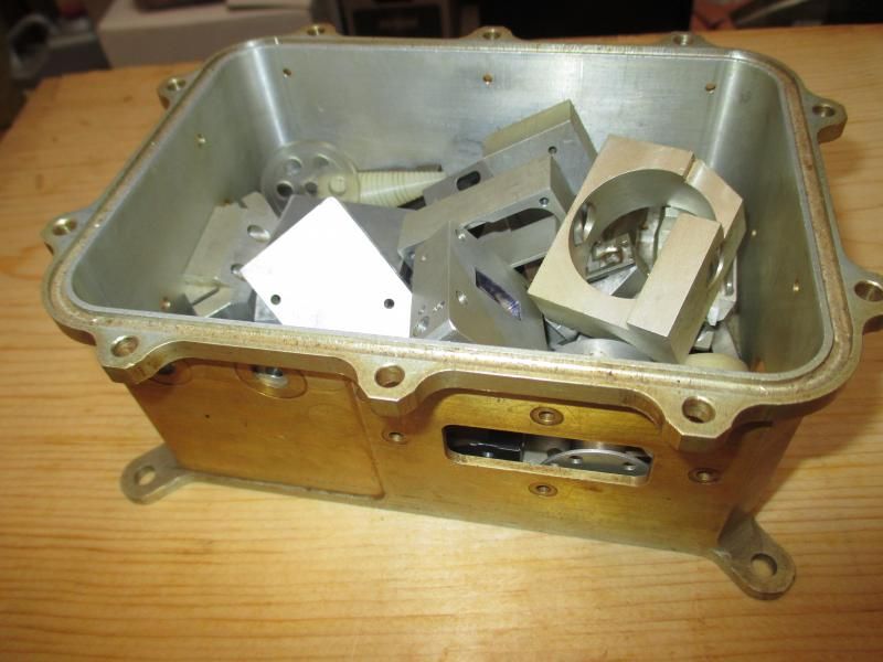
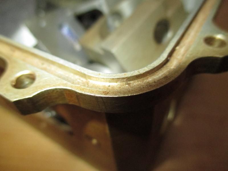
I am machining a rectangular (8" x 4") oiltight enclosure from a solid acetal block, and I need to cut an O ring groove around the top surface to provide a seal for the lid.
The groove will be 1/8" wide and about 3/32" deep and I need to radius the groove at the corners to about 3/8" radius.
This will be machined on a Bridgeport manual mill with DRO.
I had considered making a template and using a woodworking router with an appropriate guide bush to cut the groove but this seemed a bit of a cop out.
Does anyone know of a clever wheeze or setup which would allow me do this quickly and accurately on the mill?
Thanks in anticipation.
Jack
 
Can you just trepan 4 circles and then just mill grooves to the tangents? You'll have "breaks" in the channel on the inside, but will it matter? Just a thought.... I'd do the router bit, as the only other way I can think of is using 4 separate setups in a rotab....
 
Well... I got a couple of tricks that I use for that very same project. I've got a K&T die mill and a volstros die head. Might be an excuse to buy one or the other...
 
Before getting CNC I didn't hesitate to calculate XY coordinates and step the moves to simulate arcs. You'd need to use fairly small increments to ensure smooth enough scallop height for sealing but it's certainly do-able.

Router + template sounds like the easiest, low-tech method absent access to CNC or Volstro head, etc.

-Jeff
 
I have had to do this type of thing before and without a CNC it is kind of a crap shoot. Since you are doing this in acetal you can be rather creative. If it were me I would either freehand it with a 1/8" ball end mill or use a template. The problem is you have to make the template which leads you to the same problems. Again, if I was doing it I would set my Z depth and freehand it carefully. If you haven't drunk a gallon of coffee or try to do it when you have to take a leak you can make it look darn close to a CNC job.
 
Beware of ''stepping round'' corners for O ring grooves, shall we say, (I'm being diplomatic here ;) ) the surface finish requirements may be met??

Same with a router and template, added to which many routers do not have preloaded bearings so there is by nature slop in the spindle, which WILL show in plastics.
 
If you go down the rotab route ,a few tips .


If this is a rectangular block where the groove straight sides are equidistant from the edge ,that makes things a bit easier , put the straight sides in first ,take plenty of care to get them the correct distance from the edge and the depth must be spot on.

Set the rotab on the spindle centreline ,mark the center of the radius on the job ( this could have been done while doing the straight grooves) ,clamp the job to the rotab using a center in the spindle to locate ,once clamped down a finger dial indicator can be used to check that the start and finish of the rad are on center to ensure a good blend.

To actually cut the groove should now be easy ,just move one axis of the machine to get the required rad and cut away ,use the graduations on the rotab to get 90 deg. take great care on the depth as you don't want a step.

If you have succeeded in positioning the straight grooves ,it should be possible to arrange some stops on the rotab to push the other corners into rather than having to set each one up ,this will also save re setting the rotating positions as well.

This all reminds me how good it is to have a CNC mill ,even the slowest and most inefficient CNC will leave the manual guy standing on jobs like this.
 
Here's a part I made 42 years ago. Had to make three of these, the one shown was the set-up piece, hence the dings. (Machined from solid 6.0 x 7.2 x 3.0 6061) Used a Kondia vertical turret mill & a Troyke rotary table. Made a fixture using pins to locate the part. I believe the o'ring groove was .140 +.002/-.000. Oh yeah, NO DRO. We ended up getting a Moog Hydra Point when we landed the production quantities.

parts003.jpg


parts002.jpg
 
"Wrong the forces on the o-ring are equal until they attempt to send it out the crack in between the 2 housings."

The side walls are there to keep the ring in place. If you don't think it really seals on the bottom surface
of the groove, try making the bottom surface with a step as mentioned to *avoid* above and see how
far you get.

You're right Jim, that's why I posted the image page. Shows what we can't see happening.
 
Gentlemen
Thanks for taking the time to post the ideas and examples. I think my simplest route would be to try and source a Volstro rotary head, but I don't see too many for sale here in the UK. I'll keep looking.
The idea of the rotab with an X-Y table fixed on top is also interesting, and the link to the .pdf document was very informative. I have the necessary parts so I might give that a go. I think my X-Y table has sufficient range.
Once again, thanks for your interest and help.
Best wishes
Jack
 
Gentlemen
.. I think my simplest route would be to try and source a Volstro rotary head, but I don't see too many for sale here in the UK. I'll keep looking.

I'll be selling one sometime in the not too distant future, once I've replaced the broken bevel gear inside it.
Been sitting like that for a while now, just haven't got around to fixing it yet.
 
I would say you had it right on the first thought if you wish to get this done with existing gear- use the mill as a pin router.

Lock axes.
Secure aluminum plate on table- plunge to bore and set 'pin'.
Make up template and double side tape(or other dodge- could be milled recess for part) to bottom of work piece.
Set over pin.
Raise table to hit your cut depth.
Manually feed (by hand not screws) to cut groove in work.

This leaves you with the challenge of making up the template but simple enough with a router/guide bush.

More work?
Depends on how many parts to run off of setup..
The advantages are that while you might screw up once or twice making the template but once made, your real parts can be reliably run and will all be the same.

I don't think I would try this on steel, but will work fine on plastic parts with this small groove.

The template BTW must be be a groove and is cut to width of pin used.
 
If it's just for a environmental (non pressure) seal, another option is to cut a 45 degree groove across each corner and just radius the sharp corners with a die grinder.

I've done this for vacuum chambers and it worked fine. For that matter, unless it's a customer part a square groove will work fine also. just radius the corners so the o-ring doesn't get stressed.

Another way to do it in the mill is a variation of the pin router concept.
Make a template by hand the same dimensions as the inside of the groove. Clamp the template to the mill table, and fix a pointer/guide that's the same dia. as your cutter to the mill frame. To mill the corners you manipulate the X and Y handles to follow the template. Of course the straight parts are easy, just when you get to the corners you need to keep an eye on the template and follow the radius with the guide pin.

Chris


Back
Top