My particular "Quartet" was already made into a "Sextet" combo mill by Abom79, His Dad, Grandad, or perhaps the PO they had bought it from, I know not which.
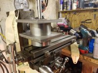
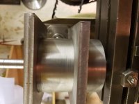
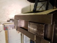
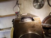
What was done was actually a low risk, minimally intrusive modification. A clearance, not high-precision, hole was burned into a slab of steel plate, its vertical edges dovetailed, holes drilled and tapped to face-bolt it AROUND the horizontal spindle.
What made it "easy" is that the surface it is mounted to is already flat and in-plane, not a curved casting surface.
In that position, it interferes with
nada, so remains in place all the time.
If/as/when need be, a K&T vertical slotter head is attached with the dovetails and driven from an adaptor to the 40-taper, just as it would have been driven if on a K&T mill.
OR
A swiveling K&T Universal all-angle head is installed, same dovetails, similar drive off the 40-taper, just as it wudda been driven on its usual K&T horizontal "mothership".
If you can "permanently" install a similar dovetail-edge plate on your mill in a similar manner, there isn't much limit on stuff you can use it to anchor.
Whether driven from the spindle or powered some other way, it is already and always in proper alignment to the knee's goodies as well as the spindle. My "add ons" only need hand-adjusted vertically so their driving adapters have proper gear spacing. Even that would need but a dowel-pin or shoulder-bolt to nail-down.
2CW[/QUOTE
If I understood this reply I would comment on ,I don't so I can''t.... wait ,I've read it for a 5th time

, I don't think you realise the size of the Centec 2 ,The head on Adam's K&T would be about the same same size (maybe a bit smaller
)
sean


")
.jpg")

 )
)
 .
.