What's new
What's new

Need compouind angle help PLZ

Finegrain

Diamond
Joined
Sep 6, 2007
Location
Seattle, Washington
Hi guys,

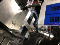
I need to put this compound chamfer on this part:

Compound angle.jpg

Part is 5.4" tall, and the chamfer is defined as .30", 45* on all 3 axes. So, looking at it from the front, the line where the chamfer starts is 45*. Same when looking from the right or the top. I'm pretty stupid when it comes to how to make compound angles :nopity:.

Next challenge after figuring out what the angles are is how to mill it -- I first thought I'd just set the head of the manual mill to the right angles, but that's no good since the table is still going to move in plain old X and Y. Then I thought maybe I could get the angles right, then plunge an endmill into the corner, but that seems a bit sketchy.

Last resort is to just stick it in the VMC and let CAM figure it all out. But, I would like to know how to do this, in case I get something down the road that won't fit in the VMC or would be a PITA to fixture in the VMC.

Thanks, and regards.

Mike
 
Looks to me like all you have to do is set the part up on a 45 degree angle in two directions and run an endmill over it. the .3" is typically the measurement of the sides of the triangle formed, indicating depth of cut.

The hardest part, as usual, is fabricating the jig. A couple of angle plates and creative clamping is where I'd start.

The setup would be just like your picture, except the 'L' would be down. In other words your drawing shows how the part would be oriented for milling the flat on the other edge of the long end.
 
set the part at a 45 angle then mill with a 45 deg cutter

That's the easiest way right there if you're going to do it manually. CAM wise that is just a 45 corner on a rectangle so no trickery required there, .300 down, .300 over.
 
put a vice in a vice. or are you trying to figure out how much to plunge?
 
set the part at a 45 angle then mill with a 45 deg cutter

I don't think this does it. I tilted the part (in CAM) 45* and looking at it from the side, the angle of the chamfer plane is ~55*:

Compound angle side view after 45 tilt.jpg

Sorry, the screenshot looks like poop, don't know why. But you can see that the angle of the cutter that would make the chamfer is not 45*.

But this gives me the idea to tilt the part 45* in the vise, nod the head 35* (90 - 55), and just hit it with a regular endmill.

Regards.

Mike
 
ive made a very similar l bracket with a .200 depth. dont "tilt" the part, Rotate it on a flat plane(if doing manual) if your doing cam then just program a 45 cutter at a 45 deg angle across the corner
 
That rather casual definition of the chamfer suggests the angles aren't critical. Most likely derived separately for each plane to ensure clearance at intersections.

If that's the case easiest way is to work backwards using the chamfer plane itself as the reference. Thinking like an inspector I guess. Compound angles get really tricky if you need to reference off the sides of a part or a line parallel to them which is what happens when you do a simple tilt in CAM or 2D CAD. Working off the chamfer itself the reference lines, in your case, run at 45° across the part.

Time I did something similar I started off by setting the piece in a tilting vice with the largest side against one jaw and vertical in both planes. Then I rotated it about one corner to get two sides at 45° and tilted the vice 45°. Sliced the corner off with an ordinary end mill. Job done, customer paid so I guess it passed QC.

Clive.
 
That rather casual definition of the chamfer suggests the angles aren't critical.

Having seen the purpose of this compound-angle chamfer, you are certainly correct! However, all it takes is a QA guy at the customer site having a bad day and actually measuring, and failing the parts :rolleyes5:,.

Looks like I have a couple options. Thanks guys!

Regards.

Mike
 
Part held at 45*, head nodded at 35* (no idea why the uploader rotates the image, it isn't that way on my PC :toetap:)

IMG_0104.JPG

Nice 45* as measured from all 3 sides :).

Regards.

Mike
 

Attachments

  • IMG_0104 rotated.jpg
    IMG_0104 rotated.jpg
    44.2 KB · Views: 101


Back
Top