What's new
What's new

Need help setting up the forward / reverse drum switch on my split phase motor

lo7us

Plastic
Joined
Oct 11, 2014
The challenges keep coming as I discovered that the "Powr-Kraft" (Montgomery Wards) 1/4 HP 1725 RPM Split Phase motor that came with the lathe was missing the "drum switch" to allow forward and reverse. So I bought a Dayton (2X441A) drum switch, and see that my motor only has two wires, and the back of the motor mentioned "switching polarity of the wires to reverse direction.

Hum, this seems simple enough, but I'm once again hoping someone has the wisdom to make sure I don't fry the motor (or myself!).

I read about how to set this up IF my motor had 4 wires to set-up, but it does not (see photos). I appreciate the help and will make sure to post the results once I figure this out. Thanks in advance.

IMG_1826.jpgIMG_1827.jpgIMG_1828.jpgIMG_1832.jpgIMG_1834.jpg
 
AC motors with only two connections inside are not meant to be reversed. Motors for cheap air compressors or other things that only run in one direction are often built that way to keep down the cost. Those empty square holes on the board are where the maker could have brought the leads for reversing. If you take the whole motor apart, the leads might be accessible so you could reconstruct the wiring for reversing. I think the Monkey Wards motor looks to be about worthless, so you will be better off to replace it and go a bit bigger like 1/2 HP while you are at it.

Larry
 
The data plate states switching the red and yellow to reverse.
The studs must have wiring going back inside the motor behind the insulator for that to work

If you have to use this motor I would start by switching them around to see if it will indeed reverse.

If it doesn't I would find a newer motor that had reversing capabilities clearly stated

Mike
 
If reversing the yellow and red do indeed reverse the motor, and are the motor connections to 115vac line then the drum switch will work.
Using this diagram: https://www.google.com/search?q=day...ustanswer.com%252Fhvac%252F6kseh-ra-150.html&
Ignore all the T numbers entirely and just connect the L1-L2 115vac as diagrammed and connect the motor yellow/red wires to switch #3 and #4. You will have to determine whether
yellow should go to #3 or #4 by the direction the motor turns.
 
First, since the name plate has instructions for reverse, it probably is reversible. The red and yellow wires probably go to one of the two coils in the motor. The other coil is undoubtedly connected on the back side of the terminal board.

You need to disconnect the red and yellow wires and extend them to the switch. You also need to add two new wires from the two terminals to the switch: I would suggest two different colors. Hence, a four wire cable and all four wires need to carry the full motor current.

As for the connections to the drum switch, you need to consult the wiring diagrams that came with it. Look for a single phase, two coil motor diagram or one for a DC motor. If you can post a photo of that wiring diagram, I can work it out. I looked on the Dayton/Grainger site but could not find specific information on this switch.

Do not use any generic "drum switch" wiring diagram as drum switches ARE made with different configurations. And a dead short is possible if you mix them up. BIG SMOKE CLOUD and LOUD NOISE!
 
Thank you all for the response... I'm still a bit confused so I'm going slowly as I proceed if I understand correctly, based on the two wire and ID plate specifying it's reversible, I deduce that yes if I separate the wires from the terminal plate, I will have two separate circuits, that when energized (separately via the drum switch), will alter rotation of the motor. I will investigate the back of the motor terminal to verify it is not just a junction block. I will post more photos and set up a safety circuit to try a bench test. Oddly confusing for what I thought would be a simple issue. Worst case is I will replace the motor with a. 5 hp oh then I need to determine the logan 200 motor pully sizes since the manual mentioned the pully should have two sizes. Anyone happen to have a logan 200 to measure the diameter of these pully sizes?
 
Here is the wiring diagram that was inside my Furnas drum switch. This is probably the most common type used for reversing motors but, as I said before, you MUST insure that yours works the same way before wiring it. You should verify that the internal connections are the same as what is shown in the top center part of this diagram. I believe my 115 Volt motor is similar to what you have and I am using the upper right diagram labeled "Split Phase".


If you use this connection diagram, you must supply the line power at the switch, as shown, NOT at the motor terminals. The switch should then disconnect both coils from power when it is in the center or OFF position.
 
Working wiring diagram for single phase to drum switch

Ya I successfully installed my Dayton drum (Forward / reverse) switch to my split-phase motor, and it operates perfectly, both forward - off- and reverse. Here is a drawing that "Glen" did on "justanswer" :bowdown:

Single_phase_drum_switch_wiring.jpg

Thank you all for your help and I hope the attached photo helps other people wire their single phase motors to drum switches. (whew, sill it was a bit scary :eek: when I tested it!)

Oh my motor had only two wires and the instructions on the back said to to switch wires to change direction, and after careful inspection, the two wires (detached were one circuit, while the other two wires on the terminal board was the other (direction) circuit. After detaching the two wires I had the needed four wires as indicated in the attached diagram.
 
Last edited:
confused with colors

Ya I successfully installed my Dayton drum (Forward / reverse) switch to my split-phase motor, and it operates perfectly, both forward - off- and reverse. Here is a drawing that "Glen" did on "justanswer" :bowdown:

View attachment 135307

Thank you all for your help and I hope the attached photo helps other people wire their single phase motors to drum switches. (whew, sill it was a bit scary :eek: when I tested it!)

Oh my motor had only two wires and the instructions on the back said to to switch wires to change direction, and after careful inspection, the two wires (detached were one circuit, while the other two wires on the terminal board was the other (direction) circuit. After detaching the two wires I had the needed four wires as indicated in the attached diagram.

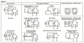
You have the orange wire labeled as T=Orange. Which "T" is it?? I've got a Dayton Motor (3K617C), with all yellow wires, with the wires labeled P1, P2, T1, T2, etc. I'm assuming it is T4, since it is the only one left.

Your diagram is the FIRST one I've found that associated color with P & T labels!! Thank you, thank you, thank you!! I'm trying to switch out a 60 year old 1/2 Hp motor (before grounding plugs, etc.) on my Atlas 618 for a 3/4 Hp Dayton to get more UMMPH in my lathe.

I've got a Furnas Electric (out of Batavia, IL), style A-14 drum switch, and it's built like no other drum switch I've researched so far. Instead of 3 leads on each side, it's in a 6-point star configuration (two line-in, four line out=W, Bk, Rd, Gr[NOT ground]), and the moving part (rotor?) is solid -- pre-wired in bake-lite. I'm assuming I could just match up T5, T4, T1 & T8 with the four-line out.

I found an identical problem at The Home Machinist! ? View topic - Reversing switch wiring how to question. , only the leads don't use P1, P2, T1, T@, etc. I can probably assume (from the 2nd jpg, inside middle right) that lines 1 & 3 go to the starter windings, which would be line T5 & T8, and Black line-in goes to "A" and White line-in goes to "B". Leads 2 & 4 have different colors (in 1st jpg), so not sure which would be T4 & T1?? Would it matter, since power would be sent first through either (depending on direction)??

I'm also assuming that the Furnas Electric R1 drum switch (in EPAIII's post, see 3rd jpg) is different from the A-14, since the split-phase diagrams are also different. From the wiring of the switches, they seem identical! So, are the corresponding leads (lines-out, line-in, starter windings) on opposite sides (as in the 2nd jpg, split-phase), or mirrored, offset by 2 (as in the 3rd jpg, split-phase)??

Will it be possible to re-wire this, or do I have to bite the bullet and purchase a more "modern" drum switch (like the Dayton)?? Very confusing!

Any help would be greatly appreciated.
 

Attachments

  • FurnasA-14.jpg
    FurnasA-14.jpg
    70.2 KB · Views: 32,660
  • FurnasA14Switch.jpg
    FurnasA14Switch.jpg
    69.8 KB · Views: 48,407
  • DRUMSW7E1_zpstltuuxs2.jpg
    DRUMSW7E1_zpstltuuxs2.jpg
    41.5 KB · Views: 5,091
Orange is T4. The furnas is different than the Dayton I installed. Your assumption on wiring sound good. But as I mentioned, I opted for the Dayton drum switch.


Back
Top