What's new
What's new

Newbie helical gear cutting

crystalltiice

Aluminum
Joined
Jul 31, 2015
Hi,

I'm trying to cut a helical gear on the mill. Looks to be 12DP and 43 teeth from reverse engineering the pinion.

It seems there are three methods by which it can be done:

1. Involute gear cutter (bought or home made)
2. Fly cutter - think it might be tricky getting profile right.
3. Gear hob - most universal

All using the universal dividing head connected to the lead screw, head tilted to helix andgle.

The Gear hob looks best as one cutter can cut any number of teeth so no need to make 8 cutters. The questions is, can a Helical gear be made like this. Is the hob dimensions still the same, or does it need to look more like a thread/spiral profile? The ones I've seen for straight spur gears are parallel grooves with rack profile.

Never made a gear so this is all new to me, but willing to try!
 
The big question is are you trying to cut a gear to fit a mating gear? If so and the service requires precision, quiet operation, and longevity - an automotive transmission for example -you're biting off a big chunk.

If you can find a gear hobber or universal mill, the gearing to make it all work, and a hob you can make an excellent gear. You do have to have a universal mill because of the helical gear's lead angle and the hob's helix angle.

We can write pages but it would simplify things if you stated your gear's requirements and service,and listed your resources and had a hob handy. You can cut a pretty good gear single indexing a formed gear tooth cutter but in a powered transmission it may be noisy. Stacking a row of formed gear tooth cutters to emulate a hob plain wont work. Flycutting a gear is a recipe for the cutting edge to fail at critical moments and the process will take days.

So hob it if you can.
 
Ok fair enough.

A friend of mine could make any gear under the sun on his mill. Unfortunately he is no longer with us mentally, or rather not what he used to be, but I have all his equipment including the Lagun mill, universal dividing head with change gears and one mounted to end of lead screw, some DP form cutters (but not the one I need) as well as an assortment of homemade form cutters and a selection of homemade hobs (I have not checked to see what he has as they are not all marked and I was also under the impression that they are meant for straight spur gears not for helical)

So, the things I'm lacking is the knowledge and experience (and maybe a few other things?) but the will is there.

The gear in question is from a golfcart transmission/differential. If you look at the gear now, or rather whats left of it, it would seem no amount of noise would cause any alarm with the driver, so we should be good in that department!! The gear is also not hardened, the 16 tooth pinion however is and to my untrained eye looks quite good.

I hope this give a better picture of my situation.
 
... I have all his equipment including the Lagun mill, universal dividing head with change gears and one mounted to end of lead screw, some DP form cutters (but not the one I need) as well as an assortment of homemade form cutters and a selection of homemade hobs (I have not checked to see what he has as they are not all marked and I was also under the impression that they are meant for straight spur gears not for helical)
Look at your hobs. If they are actually hobs, you will see that the teeth revolve around the body like a thread. To cut teeth, the part needs to rotate in a timed relationship with the hob. The relative motion between the straight sides of the hob teeth and the rotary motion of the blank create the curved sides of the gear teeth.

I don't think you are going to do this on a vertical mill.

Hobs can cut spur or helical teeth, no problem. They also generate involute teeth.

Form cutters do not cut involute teeth, they are sort of a compromise. But for what you want to do, you can probably get away with a milled part. Can't hurt to try anyhow, and if it breaks it breaks.

To cut a helical gear on a mill you need to have a dividing head that can be geared to the table, so that as the table moves the head will rotate. That's where you get the helix.

Generally people prefer to do this on a universal horizontal mill because it is easier to get all the angles you need. But you could do it on a vertical if you are stubborn and patient and resourceful :)

Find an older "how to run a milling machine" book and there will be descriptions and photos of what you need to do.

Have fun :)
 
All using the universal dividing head connected to the lead screw, head tilted to helix andgle.

Absolutely not happening since table travel is NOT parallel to axis of DH axis

This is the reason for the existence of UNIVERSAL horizontal mills - whose tables (and therefore travel of table) can be swiveled to helix angle

EXCELLENT clear descriptions from 101 years ago here

Internet Archive: Error
 
Sorry, I meant milling head/cutter tilted, not the dividing head!

The hobs, if I remember correctly had grooves cut not a spiral, I'll check tonight. Question is, if it is just grooves, will it cut a helical gear on the mill using DH? Alternatively it looks like a B&S type cutter at the correct helix angle will give a satisfactory result.
 
Forgot to add, my friend never had a gear hobbing machine, only other machine was the NO2 Cincinnati T&C grinder and the Colchester lathe. He made excellent gears with that combo.
 
Head Set To Helix Angle Brown and Sharpe

Cutting helical gear with vertical head set to helix angle... Brown and Sharpe

Ramsay 1:)
 

Attachments

  • IMG.jpg
    IMG.jpg
    68.7 KB · Views: 1,370
By far the most difficult aspect of helical gear cutting is determining the exact, correct helix angle. It's annoying as hell when you cut a nice gear and then find that it won't mesh with its axis parallel to the mate :D Guessed helix angle = wrong lead = tooth thickness wrong, etc.
 
SeaMoss I hear you but my friend was a master and I saw the engineers blue transfers, he never had any comebacks and did jobs for very expensive repairs. He must have done something right!

HuFlungDung (Nice book btw), that is slowly sinking in. The other problem is once you have magically managed to measure the sample gear, you still have to set the machine over to the correct angle as well!!

My thoughts were to mount the pinion and use a DTI against a tooth to get the lead angle right.

There is always MDF or cheap engineering plastics to start with...
 
Unless the pinion has the same number of teeth as the gear you have to cut, you cannot use the lead obtained by trial and error for the mate. The helix angle will be the same but the lead changes for every tooth number.

Finding the lead by trial and error is a major PITA because every gear train you set up can require a lot of time to make it all mesh.

Far better to know the exact center distance of the two gears, within a thousandth or two, then the helix angle can be calculated, then the leads derived from that.

You should search these forums, this has been discussed many times already.
 
If you need to get a cutter, I believe the cutter number will be different for the helical gear. Research cutting helical gears with cutters.
 
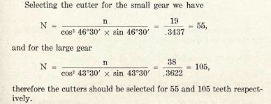
I have read somewhere that there is a correction factor based on the cosine of the helix angle to get a "new" number of teeth which needs to be used to select the cutter number, or at least something like that. This helix angle is about 15deg. I don't have a set so will have to make what ever I need.

Ok, might have to put the old gear in then and try and clock that up rather?

Something else: I understand from a theoretical point of view the B&S cutters are a compromise as only the start number on the cutter is correct. Understandably it reduces the number of cutters required by cutting a range of tooth counts each.

This being said, if you were to make the required form cutter using the same formulas but instead of trying to cover the range, you focus on the tooth count you need. You should be in gear hobbing machine accuracy territory, not so?
 
Actual number of teeth/cube of cosine of helix angle = number of teeth which you use to find the range required of the involute cutter.

Although you can check the lead you intend to try on the old gear, like I wrote, finding the lead by trail and error on two sets of compound gears is next to impossible. Why can you not measure the exact center distance of the two gears? You do have a Machinery's Handbook with lead tables in it, right?
 
OK, my two cents' worth: (1) If you want to use this project as a time-unlimited learning experience, be prepared for an unbelievable amount of unpleasant surprises. (2) If you just want a gear that works, try to buy a new one or, failing that, send the dead one and its mating gear to Welcome to rushgears.com - Nobody makes custom gears faster!!! for quote. The price will provide a good indication of how much more is involved than appears at first glance...
 
Helical Gear

Here is a gear I cut for my std hi speed milling head on my 2h plain horizontal.. I cut this gear on a 2hl Kearney and Trecker universal so I was able to offset the table to the helix angle..

The gear produced in this manner obviously is not as good as a factory gear but it can mean the difference between an attachment you can use on your mill or an attachment you can use to anchor your boat...

Ramsay 1:)
 

Attachments

  • K&T gear cut.JPG
    K&T gear cut.JPG
    91.3 KB · Views: 2,436
Well I want to learn how to cut a gear, I have the opportunity to do so whilst possibly earning some money. I'm currently sitting at a 50/50 point if I should get someone else to make it or DIY it. This is spare time I'm using so any money is welcome.

I have the hardened pinion which still looks fine, then I also have a POS with 1/4 circumference which is smooth to the root and the rest looks like razor blades on edge.... oh, that's the gear!

Somewhat difficult to do the reconstruction without the actual housing everything fits in. I quoted the same as the most expensive quote I got, which is about double the cheapest.

My plan is: make cutter, make blank, make stuff up, make phone call to gear supplier.....

Last two are optional, but learning will be compulsory! I had a digital copy of machinery handbook but it got lost. Maybe I must try and find another and compliment the other reading I've done thus far.

I also need a change gear for the lathe, straight MOD spur gear for which I have the cutter and sample.... not so urgent but certainly a much shallower end to take the plunge in.

Thanks for all the valuable info, I'll let it soak in, and then come back for more if the quote is accepted!
 
"new" number of teeth which needs to be used to select the cutter number
Tid bit from the 1916 scan - thumbnail

should be in gear hobbing machine accuracy territory, not so?

Hardly - no off the shelf form cutter will approach HOBBING - which is a GENERATING process not not concerned with form of cutter
 

Attachments

  • Selecting cutter.jpg
    Selecting cutter.jpg
    67.3 KB · Views: 727
I don't think you are going to do this on a vertical mill.

its been done,. One of the guys here, I believe unfortunately he's passed away, had a clever set up for it.. The difficulty isn't that its vertical, its coupling the spindle to the work....easily done (relatively) in this day and age with electronics rather than gears. Drive an encoder off the spindle, do some math with the signal, then have a servo or stepper drive the dividing head. John Stevenson has done the same on his universal horizontal to hob helical gears.


Back
Top