What's new
What's new

Lapping a 4° Internal Taper

RDL

Stainless
Joined
Jun 5, 2005
Location
Edmonton,Alberta,
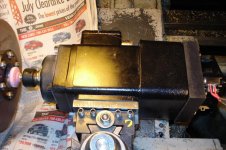
Before going any further I thought that it might be a good time to get the technique "calibrated" on the forum. I have not lapped a taper before therefore I can only imagine what is required - which is not the same as having experience. The first iteration Lap was solid to the Tailstock but the Internet advice was to have a sensitive feed. Pictured below is the modified version which has a 3/8" guide on which the reamed Lap slides. The feed is finger controlled - well that is the plan. There are three laps for various grit sizes.
MT3 - Lap.jpg

The Impeller taper is cut using the same 4° Taper Attachment settings as used for the Lap.
Impeller - Lap.jpg
The center hole was drilled under size then opened with a small Boring Bar. The next step is to use the Taper Attachment to machine the proper internal taper.

Usually Lapping is done after grinding so I do not know what to expect if it follows a FF insert. I've tried grinding which was good, but not so good (I used the Compound instead of the Taper Attachment). FYI the Lap, pictured above, has a turned finish. Lapping speed is estimated to be about 200 RPM and sprayed with Varsol or WD40

I have the following Lap Grits 90x - 280x - 400x - 600x and several diamond pastes which I don't think will be required.

Suggestions or Flames ?

Raymond
 
No, but questions ..

- This is post #1, but it starts part-way through a task and sort of alludes to a back-trail. Is there such 'history' already on PM?

- Suspect it would be helpful in enlisting advice from those who have passed this way before to ID the materials involved, (alloy, hardness...) their thickness, mass, RPM intended, desired level of precision, any other indexing or retaining mechanisms besides the taper alone...(probably sources of distortion) yadda yadda.

Suspect the techniques differ dramatically between and among Aluminium or copper alloys, steels...... Inconel.... Noryl, even?

Bill

Bill,

There is no prior post about this. I did a Search but I did not find appropriate information.

The 4140 8" Impeller turns at 15,000 rpm. It currently operates at 250°C (just great for bearing anecdotes).

After making the tapered connection the Impeller is rotary balanced to G0.4 .
The axle has a 1/4" female thread in the end which tightens a semi-cone that keeps the impeller in place.

The Impeller was centered to ±.ooo25 and the axial displacement at the periphery is .001" . There is a bit of a gap between the Impeller and the Blower Case but inaccuracy will place the balancing between difficult and impossible.

The taper varies from slightly larger than .5" to .66"

The Laps are made from Brass.

Raymond
 
From my experience, there is nothing to be gained in making full revolutions while lapping.

That is, hand actuation is more effective than spinning machines .

If you feel that the machine set up is important to improve or maintain alignment and geometry, You will want to improve the hole preparation, and reduce your expectations on the amount of material to remove by lapping.

Charge the lap by rolling with abrasive over a hard surface, (between hard surfaces)
Insert charged and wet lap into the work by hand and give several 60-90 degree twists. Withdraw lap, and revolve at least 120 degrees.Repeat as required. Inspect lap frequently. clean it,but don't remove the charge, only the swarf.

Test your work with a clean, blued plug regularly.

Don't get the plug stuck! Ask me how I know about that ;-)
 
From my experience, there is nothing to be gained in making full revolutions while lapping.
That is, hand actuation is more effective than spinning machines . ...

Good Points! I modified the setup because there were anecdotes about sticking the Lap into the taper. My Plug has an internal thread that can secure an improvised Slap Hammer. That would really do wonders to an accurate setup.

I will try to lap by hand first. The Layout Blue, on a plug, should quickly indicate a sign of progress. Is rocking the Lap better than turning it ?

I have a bearing on a shaft to work in the Charge.

Raymond
 
I echo Athack's question , "Why lap?"

A taper fit seems a good idea for your impeller, they transmit torque well, and maintain concentricity. But lapping a taper, seems to me, is a problem, because the lap cannot move over the surface to have a generating action. It will "bottom", and will distort the taper rather than improving it.

I'd grind. High-speed machine tool spindles are, perhaps for slightly different reasons,as demanding applications as yours, and are AFAIK ground not lapped.
 
Hi Raymond,

Not sure if I missed something...but what do you wish to achieve by lapping?

Athack

The Impeller has to be balanced before it is placed on the Blower Axle. When turned parts were used the repeatability was lacking. When we started to grind both faces of the taper it was possible to balance the Impeller, remove it, turn it, and re-install it without without wildly changing its balance.

The axles are made in greater quantities and are ground but the impellers have been more varied which the Cylindrical Grinder companies don't like. It is a long winded way to answer your question. The succinct answer is repeatability.

Will it work or is it asking too much?

Raymond
 
... I'd grind. High-speed machine tool spindles are, perhaps for slightly different reasons,as demanding applications as yours, and are AFAIK ground not lapped.

You are already at my fall back position. I do have a high speed Spindle Motor which was used, in the past, on the lathe. It presented two problems; the grit, even with plastic protection, is not good for the Ways and I was not getting super fits. Since that first grinding experiment, using the Compound held Spindle Motor, I setup the Taper Attachment to 4°. It would have been much easier if both of the mates were made on the same machine instead of trying to match a part that is already made. It little looseness to create a vibration or lose repeatability at those speeds.

The other hiccup is getting Grinding Points with shanks that are stiffer and larger than the commonly available 1/4" shanks.

Raymond
 

Attachments

  • Spindle Motor.jpg
    Spindle Motor.jpg
    97.2 KB · Views: 548
You are already at my fall back position. I do have a high speed Spindle Motor which was used, in the past, on the lathe. It presented two problems; the grit, even with plastic protection, is not good for the Ways and I was not getting super fits. Since that first grinding experiment, using the Compound held Spindle Motor, I setup the Taper Attachment to 4°. It would have been much easier if both of the mates were made on the same machine instead of trying to match a part that is already made. It little looseness to create a vibration or lose repeatability at those speeds.

The other hiccup is getting Grinding Points with shanks that are stiffer and larger than the commonly available 1/4" shanks.

Raymond
It is geometrically impossible to grind an accurate internal taper however a small rock does a good job of getting close which entails its own set of problems mainly the need for high rpm(50,000+)
 
It is geometrically impossible to grind an accurate internal taper however a small rock does a good job of getting close which entails its own set of problems mainly the need for high rpm(50,000+)

Darn it my motor will only turn 50,000- (or 23,000 rpm) ah well, I will have to lap after.
 
It is geometrically impossible to grind an accurate internal taper however a small rock does a good job of getting close which entails its own set of problems mainly the need for high rpm(50,000+)

I thought I was reasonably trig conversant. You're going to have to explain that one.

(I grind the occasional internal taper, perhaps did not understand it was not correct?)

If you are going to grind these in house, get a cylindrical with a high speed head, or in a pinch a T & C grinder with same. Much more rigid and better designed to keep grit (& coolant) out of the ways. And angles are so much easier to tram in.

smt_SCM_bb4.jpg


smt
 
Lapping a taper might improve the roundness if done briefly, but its not going to improve the straightness or improve the accuracy of the included angle, IMO. The difference in circumferential speed at opposite ends of the taper means that the big end is going to be abraded more quickly than the small end. Now this might mean more material is removed, but it might also mean that the abrasive breaks down more quickly at the big end, thus losing its effective cutting action. It is kind of a crap shoot as to what the result would be.

You might get a decent result if you relieve the center of the taper to force contact at either end. This, IMO, is more likely to get something that positively seats, whereas I suspect that full length lapping will result in a barrel belly shaped taper with poorly defined contact.

I'd use a felt marker to draw some lines in the bore, because ink is very thin and doesn't pile up when twisted like bluing tends to. Twist the shaft into the taper and check contact. Hand polish the end that is tight. I use a piece of wooden dowel for a polishing rod. Hacksaw a split down the end so you can feed a piece of emery cloth into it and wrap it around the dowel. If you spiral wrap it the right direction, it will stay wrapped and you can keep it from unraveling by holding the loose end with a finger tip.

When its as good as you can make it by polishing and test fitting, then put some very fine abrasive and WD40 to make it wet, and briefly lap the two mating pieces together. It may make sense to run the female taper in the opposite rotation to which the original feed marks to prevent seizing, but mainly keep the abrasive wet, and clean the muck out frequently, as spent abrasive is counterproductive if trapped in the cutting zone.
 
The Impeller has to be balanced before it is placed on the Blower Axle. When turned parts were used the repeatability was lacking. When we started to grind both faces of the taper it was possible to balance the Impeller, remove it, turn it, and re-install it without without wildly changing its balance.

The axles are made in greater quantities and are ground but the impellers have been more varied which the Cylindrical Grinder companies don't like. It is a long winded way to answer your question. The succinct answer is repeatability.

Will it work or is it asking too much?

Raymond

IMO the best way to do this is with a Diamond Plated Form Tool. Lapping will wear rings into the lap and therefore into the work piece. Do a internet search for Diamond Plated Hones.

Athack
 
I thought I was reasonably trig conversant. You're going to have to explain that one.

(I grind the occasional internal taper, perhaps did not understand it was not correct?)

If you are going to grind these in house, get a cylindrical with a high speed head, or in a pinch a T & C grinder with same. Much more rigid and better designed to keep grit (& coolant) out of the ways. And angles are so much easier to tram in.

smt_SCM_bb4.jpg


smt

Has to do with the contact area .(dia of hole changes rock dosnt)

Shows up when using a rock close to the size of the hole (like the op's picture).

Gets significantly better the smaller the rock (less contact area) never goes entirely away

Not trig but tangents of 2 circles.
 
No flame but what in the world are you trying to accomplish? Sticking a 4 degree tapered abrasive loaded plug into a hole and twisting might be termed lapping by some but others would maintain true lapping is a surface generation process where quasi random motion and abrasives are used to develop accurate contours, be it flat or some version of concave, convex, cylinder ID or OD. Count me in the latter group.

The geometry of a tapered hole and tapered "lap" prevents the relative motion required to generate a surface. It simply plugs in and rotates mating the tool and workpiece, no axial displacements are useful for improving geometry.

No idea if your need is better geometry, surface finish or both of the tapered hole.


Back
Top