What's new
What's new

OT – Replacing bearing on an electric polisher

fly_sd

Aluminum
Joined
May 20, 2006
Location
San Diego,US
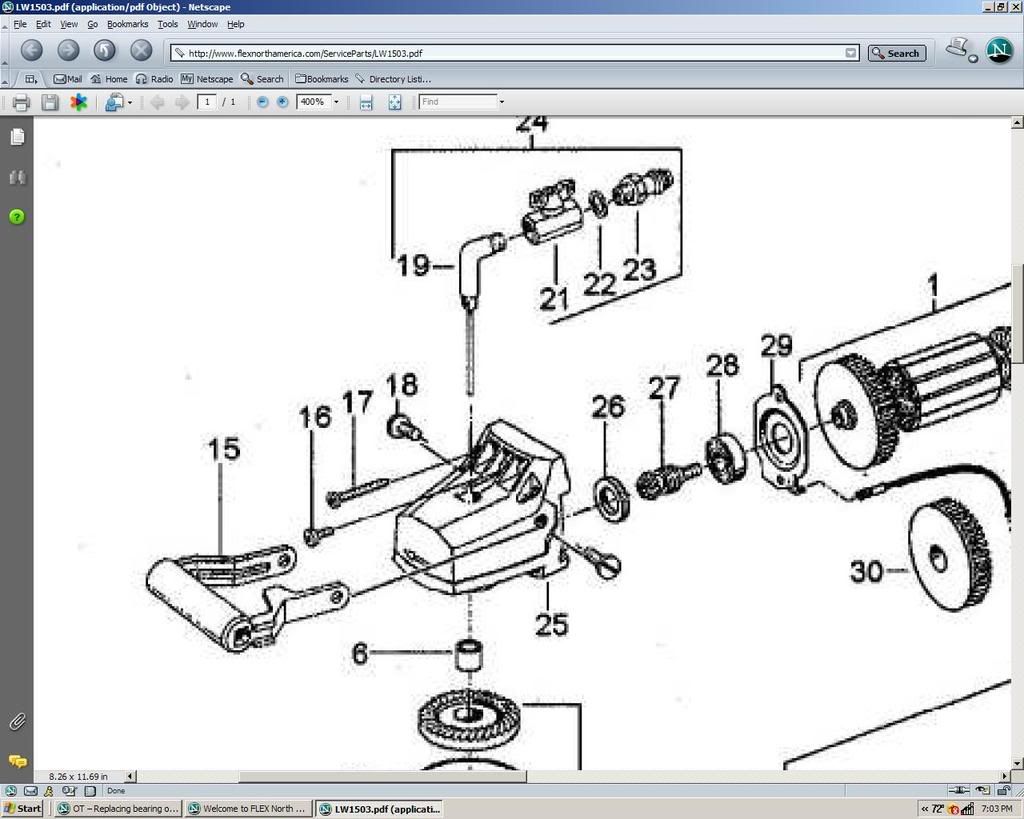
I have an electric polisher that needs new bearings so I ordered them form the manufacturer (front and rear bearing on the armature). The rear bearing was easy to replace – pressed out the old one and them pressed in the new one.

However, I cannot figure out how to do the front one. I tried pressing it out and the bearing shattered in the press. I then looked at the manufacturer’s drawing and can see that it really cannot be pressed out as I thought. Pic below

arm1.jpg


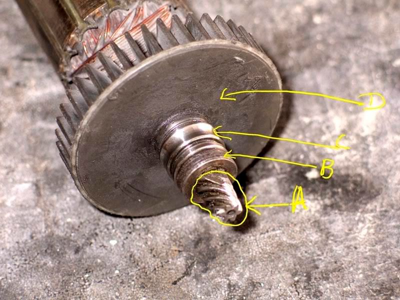
In the pic what’s left of the bearing is C. C is pressed on to A & B which is a single assembly. This whole thing is then pressed into D.

I cannot figure out how to pull out the A/B/C assembly out of D. In cases like this where a whole item has been pressed on, how can it be extracted.
 
Could you put a bearing splitter between B & C until you spread them slightly and them put the bearing splitter between C & D - Once you get a little space between C & D, I'd insert washers or equal sized drill bits and then go back and spread B & C - repeating this process until B comes off the end of the shaft.

Problem with this approach is that you might not be able to get a bearing splitter between C & D.
 
It would seem nearly impossible for the gear teeth on "A" to be machined with "B" in the way...and so I feel certain they are separate.

My other guess is that it would be an expensive route to machine "D" hub with a tightly toleranced bore such that tightly toleranced shaft "A" could be pressed into it. Also a press-fit is a poor power transmission choice in most cases without additional backing of keys or shear-pin devices.

Instead, if hub "D" and shaft "A" were made integral in 1pc, then all there is to machine is 1 precision OD for the ID of the bearing and power transmission issues are resolved by virtue of it being a solid piece.

If we go with that theory, it leaves the mystery of why "B" is even needed...a thrust surface or thrust bearing by chance?
 
Good points Matt. This is the parts drawing from the manufacturer's website (Flex)

flex1.jpg


I'm wondering if 26 is B - it looked like it was something else but given what you said that would be the most logical way to design this. In which case I guess B and C can be pressed out.
 
Great info!

Is it possible that #27 threads into #1?

I see some circular marks there...maybe...since the thing basically only turns 1 way under power the thread would be continually tightened...

This is another one of those things where it's not 100% clear...and being wrong is generally going to break something...wondering if it would be useful to spend some time trying to "drill" into the product engineering organization to get some service tips. Usually if you find the right person they're really impressed someone cared enough about their design to call and ask...and they'll give you all kinds of helpful tips :)
 
I have to go along with Matt and would say that based on the position of the bearing retainer (#29) that it looks like the pinion gear and bearing are installed in the drive head first, then secured with the bearing retainer plate. After that all you would need to do is screw the armature/fan assembly onto the pinion gear. JMHO.
 
If you are careful it is possible to grind away both sides of the bearing inner race to the point that a rap with a drift will crack it right through, that will give you a shoulder with which to remove the pinion. Tip, grind with an angle grinder cutting wheel till the race starts to show a ripple in the ground surface where the shaft would be.

Press fits are very good power transmission couplings, much better than keys, probably not as good as a fine pitch involute spline but close. There are many crankshafts held together by press and other types of interference fits.
 
Seems like 27 would likely screw into the end of the armature. The shoulder on the armature only goes halfway through the bearing, and a shoulder on 27 takes up the other half to give it good alignment.

The thread direction will be whatever it takes to be self-tightening.

You could make a cup to fit around the pinion, and fill it with molten lead to make a gripping surface that wouldn't damage the teeth. Try a strap wrench or padded pliers before going there.

Roger
 
Thanks for all the replies. I took up Matt’s suggestion and called the service company who fixes these for Flex. That was a useful call – I spoke with one of the guys who fixes these. He confirmed that the assembly is screwed in so the first step is actually unscrewing it from D.

The bearing is then pressed out.

He said that B is an integral part of the 27 can I guess they don’t bother trying to take it apart.

Good thing I called or I probably would have destroyed the armature.
 
Got it done today. From what I saw it looks like B can be pressed out also but I did not try doing that. I don't think the parts diagram shows that being disassembled but it did look like a press fit. Just tested it and it runs well.

Thanks for all the suggestions
 
The "right" phone call saves hours of grief!

Great, glad you got'r done.

I've broken too many things over the years with my own independent ideas about how to disassemble...then had to conjure up the fixes for the self-indflicted problems ;)
 
Luckily these days we can get a lot of smart people's input on this forum before we break anything. Your suggestion about calling the service people was by far the best suggestion. I thought they would be unhelpful but was pleasantly suprised when they took the time out to tell me exactly how to do it. :)


Back
Top