What's new
What's new

Pratt & whitney 30" motorized rotary table

Kurt S.

Plastic
Joined
Oct 10, 2014
Looking for any information regarding these PRATT & WHITNEY 30" HORIZONTAL MOTORIZED ROTARY TABLES.

General maintenance of them, and capabilities or limitations, specifications, etc. I have no brochures or catalogs on this table and am looking to find what information I can, hoping you can help.


Can the table be run at faster rpm with a motor change to perform in the capacity like a vertical lathe?
 
Can the table be run at faster rpm with a motor change to perform in the capacity like a vertical lathe?

Depends on your expectations, I would say. Rotary tables in general are not built for continuous lathe-class speeds. Depending on manufacturer, the bearing arrangement for the table rotation might or (more likely) might not be suitable for a conversion to use as lathe spindle. Obviously, the existing setup is also running through a substantial gear reduction, in order to achieve the torque needed for typical milling applications, so there would be mods needed in that area as well.
 
Spindle is most likely cast iron on cast iron with no provision to add lube. Probably little or no resistance to uplift so all cuts would have to be downward into the table. Anything over 1-5 RPM is going to wear it out fast. The only way to use it as a lathe would be with a powered spindle like a toolpost grinder.
Bill*D
 
My 30 weighs 1100 Lbs. Let me be emphatic - its a PRECISION rotary position tool, not a lathe

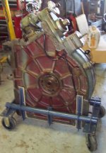
Here is mine on the cart it enjoys while not on the #3B Jig Bore by the same maker

In case it wasn't clear, the motor is for rapid positioning, not milling
 

Attachments

  • DCP_0731.JPG
    DCP_0731.JPG
    84.4 KB · Views: 325
  • DCP_0730.JPG
    DCP_0730.JPG
    87.2 KB · Views: 384
I do not necessarily agree with your comment of this being only a positioning table. This is true for jig boring, as it is all about positioning accuracy. This is not rue of other applications these tables had on other machines.

Prior to purchasing this table, I looked into some of the historical uses these tables had.

Pratt and Whitney made rotary tables for use on vertical milling machines/die sinkers, and shapers. I took notice in the shapers as the rotary tables took some abuse. The shapers also were more than capable of doing a style of vertical lathe work when the table was rotated against cutters to produce cylindrical cuts. The milling machines often employed these tables for continuous operations, with a multitude of parts about the periphery, whilst running at slow rpms allowing operators to swap finished parts without interruption.

But what the heck do I really know?

Currently, with the 1/4hp motor that was on this table (which is toast) it ran at approximately 12 rpms. I have seen these tables converted with variable speed and 1/2hp motors. I do not know if 1/2hp was ever an option.

I am planning light cutting of steel, much like a vertical lathe, and a non-production shop environment, for some special cutting to a large piece of steel (at least for what I’m doing) 20-21” DIA, 300 lbs, if I were to run it at 18-19 rpms I do not see a problem. This should keep the cutting at about 80-100 SFM.

I got this out of a plant in Detroit and can guarantee it wasn’t being used in a jig boring machine.
 
Do take into consideration it only has flat cast iron on flat cast iron scraped bearing - nearly as large as the table, with lubrication adequacy unknown to you.- and this will be moving faster than 80-100 SFM simply because its larger in diameter than your work piece

Add scan of the fact of building them circa 1948 These gents may have been the same ones that scraped the bearing side of your table and base


I do not necessarily agree with your comment of this being only a positioning table. This is true for jig boring, as it is all about positioning accuracy. This is not rue of other applications these tables had on other machines.

Prior to purchasing this table, I looked into some of the historical uses these tables had.

Pratt and Whitney made rotary tables for use on vertical milling machines/die sinkers, and shapers. I took notice in the shapers as the rotary tables took some abuse. The shapers also were more than capable of doing a style of vertical lathe work when the table was rotated against cutters to produce cylindrical cuts. The milling machines often employed these tables for continuous operations, with a multitude of parts about the periphery, whilst running at slow rpms allowing operators to swap finished parts without interruption.

But what the heck do I really know?

Currently, with the 1/4hp motor that was on this table (which is toast) it ran at approximately 12 rpms. I have seen these tables converted with variable speed and 1/2hp motors. I do not know if 1/2hp was ever an option.

I am planning light cutting of steel, much like a vertical lathe, and a non-production shop environment, for some special cutting to a large piece of steel (at least for what I’m doing) 20-21” DIA, 300 lbs, if I were to run it at 18-19 rpms I do not see a problem. This should keep the cutting at about 80-100 SFM.

I got this out of a plant in Detroit and can guarantee it wasn’t being used in a jig boring machine.
 

Attachments

  • Scraping at PW.jpg
    Scraping at PW.jpg
    96.2 KB · Views: 241
Pratt and Whitney made rotary tables for use on vertical milling machines/die sinkers, and shapers. I took notice in the shapers as the rotary tables took some abuse. The shapers also were more than capable of doing a style of vertical lathe work when the table was rotated against cutters to produce cylindrical cuts.

You mistake how the rotary tables were used on the vertical shapers. The table is a positioning table only. On the return stroke of the ram the table repositions itself slightly, and is stationary during the cutting stroke. There is no cutting force opposing the table feed forces, and all cutting forces are perpendicular or nearly so to the way surface.
 
You mistake how the rotary tables were used on the vertical shapers. The table is a positioning table only. On the return stroke of the ram the table repositions itself slightly, and is stationary during the cutting stroke. There is no cutting force opposing the table feed forces, and all cutting forces are perpendicular or nearly so to the way surface.

The Op sounds like the kind of guy who when does not get the answers he think is correct is going to go with his own WAG. Let him tear up his rotoery table or worse yet possibly hurt himself or someone else.
 
Okay, I’m reading your comments, and I did not agree that it is strictly an indexing/positioning table as was commented. That just means I have information that contradicts what was stated.

Here is an example to help clarify what I’m reading about and how they relate to these tables.

Ref: http://manuals.chudov.com/Pratt-And-Whitney-Co/Jig-Borer-Positioning.pdf

Pg 15 = “the above photos are of an aluminum piece used in a precision instrument, which requires an accurate fit with its component parts. The Pratt & Whitney Jig Borer, equipped with a Rotary Table for indexing, was used to turn the posts, to mill the flat surfaces, and to drill and precision bore the holes in each of the posts. All of these operations were done from the same table set up…….”

So from this bulletin it clearly states that they used these rotary tables in milling operations, this example of milling was rotational. Also on page 18, the description of these particular tables, it states it was designed to be used in any machines not just the jig borer machines outlined in the publication, the 30 & 24” are constructed the same. This includes precision ball bearings and lubricated.

They also differ from that of their smaller manual rotary tables in that those had additional gearing prior to the worm gears to speed them up.

Now in my project, I’m looking at some milling to be done on some specific parts, and am considering setting up a sliding tool post next to the table to take care of some critical cuts; much like a vertical lathe machine would be set up.

So if the design of this rotary table is as such to allow for milling and table was designed to carry a max load of 2200lbs and I can assume they designed it according to the operational needs that would include milling capabilities. I am looking at the reduction of the frictional forces imposed by the max load to about 1/8th and increasing from 12rpms (rated rpms) to 18 rpms while maintaining the same standard SFMs at the cutting tools.


Call it WAG if you want, sure, that’s what I would call it anyway. I was really just looking for some publications regarding this P&W table.

Happy New Year!
 
Here is all P&W would allow in the 3B Jig Bore manual as to "milling"

The spindle can be used for light boss facing. A binder A-20 on the left side of head will bind the quill in any position in its 9" of vertical travel. It is important to use this binder when performing light milling operations

They wanted to make sure you knew the machine was for precise boring and very little else.

Its easy to assume this applied by extension to any accessory made for this machine - like the rotary tables, simply because they were interested in - and hoped the customer/end user was interested in - preserving the extreme accuracy built in to this equipment
 
I've been plagued in life with people who ask me for advice, don't like the (correct) answer, then go around asking everyone they can until they find someone who tells them what they want to hear.


askhole.jpg
 
Kurt S.;3098592Here is an example to help clarify what I’m reading about and how they relate to these tables. Ref: [url said:
http://manuals.chudov.com/Pratt-And-Whitney-Co/Jig-Borer-Positioning.pdf[/url]

Pg 15 = “the above photos are of an aluminum piece used in a precision instrument, which requires an accurate fit with its component parts. The Pratt & Whitney Jig Borer, equipped with a Rotary Table for indexing, was used to turn the posts, to mill the flat surfaces, and to drill and precision bore the holes in each of the posts. All of these operations were done from the same table set up…….”

So from this bulletin it clearly states that they used these rotary tables in milling operations, this example of milling was rotational.
You are jumping from an example of a very light duty operation to general suitability for an entirely different class of operations. This generalization is not warranted.

To get back to the original VTL question, the radial load capacity of a typical rotab is neglible while the radial load capacity of a VTL or VBM is quite large. Axial load (force flat toward the table) is probably equivalent, keeping in mind the difference in intrinsic strength between a "table top" device and a machine typically tied to the building foundations. As already mentioned, a rotab is neither built nor lubricated for continuous rotation, while a VTL is.

Maybe you get lucky. Or maybe you destroy the centralizing capability of your rotab.
 
Hi John,

I have the same rotary table. Do you know the shaft or Morse taper size for the table? I am trying to buy one for my table.

Thanks,
Roy
 
Table no longer in my possession, but I'll see what if anything I can find out.

The tilting 16" has B&S 9, so I'll suppose the 30" does not have a Morse taper

Their November 1955 Circular 540-3 suggests this taper hole is only for the PROVING BAR shipped with the table - they don't bother to tell you the size:D

Following on that, it would sure make a lot of sense for ONE proving bar to fit all sizes of rotary tables I was making

If the big end of your taper hole is close to 1.060 /1.070 you can count on it being #9 B&S


Hi John,

I have the same rotary table. Do you know the shaft or Morse taper size for the table? I am trying to buy one for my table.

Thanks,
Roy


Back
Top