What's new
What's new

Q about zero distortion tubing cutting- anyone with semiconductor experience?

daveca

Aluminum
Joined
Jan 23, 2012
Location
WA State
Situation - have to cut lengths of steel (low carbon) and Al (6061) tubing from roughly 5-10" in length.

Wall thicknesses range from 060-120 thou.

For this application, zero distortion is needed, 'zero' means something like 000-002" total diametrial error

Test:

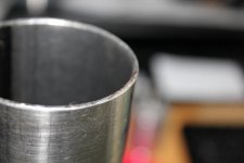
A 2.13" OD x 063 steel tube cut on a high speed chop saw with a high speed carbide blade, cuts great.
One end was the suppliers cut (bandsaw I assume) and then the opposite end is my cut.
Both have runout up to about 0055", both ends coincide (min/max dims are same location around the tube on both ends).
Thats too much! I need more like 0.002" max.

The error isnt so much "ovality" as a fairly narrow band about 1/2" wide around the point of max error,
it's not measuring 'egg shaped' as I'd expect for the term "ovality" i.e. the resulting distortion is not oval, its a round tube with two curved portions sticking out.

The distortion as measured with a bore-dial gauge ends about 3 inches down inside the tube, proving it's cutoff damage,
and not in the tube drawing. Max distortion is on the very end of the tube. Down inside the total error is more like 001-002"

It's apparently not distortion due to being clamped in the saw vise as the area clamped is not out of round, the distortion is on the end where the material is unsupported.

If I can't find a way to eliminate it, then it's onto honing, and thats expensive and time consuming.

How to fix this? Support the tube ID, during cutting, with some kind of expanding device like an exhaust pipe expander?
Straighten after cutting? How to do so without introducing ovality?
Band and chop saws cut all the way through the cross section, any benefit to engaging the blade just through the wall thickness then rotating the tube?
Is the damage due to initial contact of the blade that bends the tube or impact loading from the teeth?

Anyone dealt with this in the process of making semiconductor plant equipment?
 
What are the tubing dimensions prior to cutting?

You are in need of a high quality raw stock spec.
 
1. no lathe
2 post stated already have high quality stock, please read carefully

Nither answers the question
 
Heat buildup from cutting friction (basically it's an interrupted cut). A possible solution might be using a flood coolant and less downward feed pressure as your cutting.
 
Bingo?

How about using clamps like pipefitters use to saw through thin SS process tubing ?

That sort of gadget crossed my mind (whats left of it) but I didnt know that existed. That would support both sides of the cut and I could widen the slot to fit the blade. thanks!

It's possible the distortion is due to the little tab of metal remaining just before the blade cuts through it, that would put quite a force on the end.

I'll do a FEA simulation and see if that agrees.

To the previous poster, there is no heat buildup or coolant. It's a cold saw. There is no force to bend the tubing, my post made that clear to anyone who understands the process.

If it was saw force, the error would be oval, and it isnt.

I understand the rest of the suggestions, but they are all *way* off topic/context and do not answer the problem of getting rid of the distortion from the chop saw process. A lathe does absolutely nothing to change the chop saw process.

Why would I buy a huge lathe with a 4" through-spindle, 8 foot long, building space to put it in, skilled operator to use it for a difficult cut, to cut tubing off when the original problem is an 0.005" error in a chop saw process? That would cost me a FORTUNE in first year and labor costs. Im going to put an 8-12' section of tubing on a lathe to cut it off?

Makes absolutely no sense..
 
>002 in 2.12 X .063

Good luck with that,

Cutting metal always envolves some deformation, mechanical , heat or both . .002 out on 2.13 X 063. You can't even grip the stock with your fingers and not cause that much wow.

Best process would be to hold the stock in a 360 degree collet (fully captured conforming jaws) less than .125 from the cut, rotate the work while a thin abrasive blade came in to part the material. All while under flood coolant / lubrication. something like .002" per rev feed

Like a lathe with a wet cut off wheel.

Toothed cutters will always grab and cause distortion, that's how they throw up burrs.
Use a minimum of four teeth in the work at all times, so, .063 divide by 4 = .015 tooth pitch =66tpi if you want to continue with the chop saw approach.

Good luck! I'm sure you will find a way.

Who is your material supplier, At times I could make use of such high quality stock, do they deliver with an assurance to roundness spec.? What a boon!
 
I'll do a FEA simulation and see if that agrees.

To the previous poster, there is no heat buildup or coolant. It's a cold saw. There is no force to bend the tubing, my post made that clear to anyone who understands the process.

If it was saw force, the error would be oval, and it isnt.


Makes absolutely no sense..


Now your talking like a kid without any experience of sense.

There is ALWAYS heat. do the math.
 
Equally nearly all stock has residue stresses, cutting it any how any way releases thoes stresses. If the stocks so high quality, what about some more precise details, alloy, brand, heat treat etc? I would not expect any commercial tube at that wall thickness to stay round to within your tolerance. Its just too tight, 5 thou seams better than i would expect. You say the chop saw is high speed carbide blade, thats not a cold saw. Cold saw runs a Hss blade slowly + coolant to lubricate and cool and cuts using a positive tooth geometry to cut not scrape metal away like the typical high speed carbide blade does, totally diffrent process and could well explain your results.

If you want truly the cleanest least distortion cut, go wire EDM, totally burr free and you can easily get someone with one to cut a few, to find out just how round your tube will really stay. Tube still distorts, its a simple tubing stress issue, tube stays round its your current cutting process.
 
I have a Meyer Burger for accurate cut of grinding
It came with rubberbonded grinding disks from 0.9- 1- 1.1 and 1.2mm thick
with a machine like this you still would need a dedicated clamping device that clamps both ends of the cut in 2 exactly machined halfround jaws
A bit like that pipefittersclamp mentioned earlier

Peter from holland
 
Found it!

FOUND IT!

Sometimes it just takes lunch.

The tubing was rolled on a surface plate and that showed one high spot coincident with the measured high spot and the little 'bridge' of metal that forms just before the tube
slumps down and the blade severs the two sections apart. So, the distortion was not from cutting force or clamping force, something was distorting ONE side of the tube.

IT was also odd that the high spot coincided with the little tab left over as the blade cuts through and the cutoff section falls off. That part doesnt actually get cut off, it stretches
and shears itself off, leaving a little tit sticking out.


Pictures show it...

Computer FEA stress analysis shows the end-OD under that little bridge between the piece of stock clamped on the saw table, and the cutoff part, GROWS on the OD. (image in blue).

Simple fix, support the cutoff portion with a Vee block so that little bridge cant stretch and grow outward.

Voila, precision, no -distortion cutoff process for way less than $2000!

Cheap is good!
 

Attachments

  • cutoff 001.jpg
    cutoff 001.jpg
    97.2 KB · Views: 185
  • cutoff 002.jpg
    cutoff 002.jpg
    82.2 KB · Views: 198
  • cutoff distortion.jpg
    cutoff distortion.jpg
    55.4 KB · Views: 191
Only individual I've seen work to similar tolerances in tubing used a precision expanding mandrel in a lathe.

Where are you buying this precision tubing?
 
Simple fix, support the cutoff portion with a Vee block so that little bridge cant stretch and grow outward.

Voila, precision, no -distortion cutoff process for way less than $2000!

Cheap is good!

You weren't supporting the cut off portion from the beginning of this job? :rolleyes5:
 
You weren't supporting the cut off portion from the beginning of this job? :rolleyes5:

He wasn't using a cold saw, because those have vises that hold both halves while cutting. Sounds like he was using something akin to a Makita LC1230 dry cut saw with Tenryu carbide tipped blade -- this is a metal fabricator's saw, not a machine shop saw.
 
I would bet a precision spindle with an abrasive cut off wheel run with coolant and with controlled feed rate having both feed stock and cut-off held lightly with common holding clamp would cut clean with no distortion and the small bit of wobble to the wheel would finish both feed stock and cut stock to leave no burr.

Sounds complicated but it is only a tool and cutter grinder type machine with a holding fixture such as a split vise with a controlled feed rate. A chop saw with precision ground wheel arbor face having a positive rate feed control and a holding device would be as good.

Question is how many do you need to answer if a special designed machine or simply a feed rate device and precision arbor face truing added to a catalog cut off (chop saw) machine.

One could attach an air cylinder with a bleeder valve to a cut off chop saw handle for feed rate control, true up the arbor face having a 5/8 arbor, split a simple vise to hold two sides of the part, pad the vise, add a stop locator for measure length, add a simple coolant pump with bucket and soda water and begin cutting precision clean cuts in a day with perhaps around $500 spent.

A good wheel choice might be Hayes Abrasive tool room grade 10” x 1/16 x 5/8 arbor hole
Or Hayes TRG 10” x 1/16 x 1 ¼ hole

Using a 1/16 width is helpful to having less cutting pressure to the part.
 
How does the factory make those cuts at every 10'-12' ?

FEA analysis to find you needed to support the cut off portion ?


Back
Top