What's new
What's new

Rebuilding a Worthington Model 3B AllSpeed Srive

projectnut

Stainless
Joined
Mar 4, 2006
Location
Wisconsin
Rebuilding a Worthington Model 3B AllSpeed Drive

I am in the process of rebuilding the Worthington drive in a Sheldon lathe. I have removed the drive and disassembled it. One puzzling note is the way the bearings fit in the central housing. The OD of the bearings is 2.8346" while the bore in the housing is 2.8350. Essentially it's a slip fit. I have found replacement bearings and they have the exact same OD as those currently in the machine. There are no signs of wear either on the housing or the bearings.

The only information I can find for the bearing fit is one sentence in a parts manual that reads they are a "C3 loose fit". I'm not sure what the specification is for a C3 loose fit. While the inner race of the bearing is press fit on a shaft it seems the outer race should not be able to rotate in the housing.

Any insight would be appreciated
 
Last edited:
You should have put Sheldon Lathe in title as there is and old Sheldon factory tech who reads the board. You could also Google search. Sheldon Lathe Worthington drive Practical Machinist and look in those Archives for his posts.and private message him.
 
It is common to allow for slight rotation of the outer races of ball bearings.I have pulled apart many machines that were set up that way and had little to no wear after many years of use.Don't ever recall any tapered roller bearings set up that way.
 
You should have put Sheldon Lathe in title as there is and old Sheldon factory tech who reads the board. You could also Google search. Sheldon Lathe Worthington drive Practical Machinist and look in those Archives for his posts.and private message him.

Thanks for your response. Here's a short version of my search. I have already searched through the archives and done at least a dozen different google searches using just about any wording I can think of. It's possible I missed something in the archives, but in the several searches I've done I've attempted to include everything related to Sheldon, and Worthington drives. In addition I've done some patent searches. They have turned up information related to different model drives, but nothing specific to what I'm looking for on the 3B series. I've also spoken with John Knox of the Sheldon Lathe Group both on the phone and through e mail. He doesn't have any working knowledge, or information on this particular drive.

Part of the problem it that Worthington made several different model "AllSpeed" drives for lathes. All are very different from one another. Apparently the model 3B was only used for a few years on some M series lathes. As such their popularity, and information about them seems somewhat limited.

I've also contacted several vendors who have in past years either sold Sheldon lathes new, repaired them, or sold parts for them. I thought I may have struck gold when I contacted Bourn& Koch in Chicago. But once again no luck. They did have information on several other model drives, but not the 3B.

Fortunately most of the wear parts used in the drive are "off the shelf" and used in other applications. I was able to locate what I hope to be direct replacement bearings from a couple bearing houses. The manufacturer of the original bearings is long out of business, but using the IBI bearing interchange guide I was able to locate what I need. The bearings are currently on order, so the proof of the pudding will be a direct comparison when they arrive.
 
Addressing the bearing OD fit:

Rolling element bearing outer races are typically a small clearance fit in their housing bores - in this case the ID of the housing is larger that the OD of the bearing out race by less than a thousandth, proportionately more in larger bearings. The alleged object is for the outer race to rotate in service very slowly (a rev per day) to distribute wear. Seems to work: most failed bearings I've removed and examined failed on the full circumference of the outer race.

If unitized rolling element bearings were interference fitted on the OD as well as the ID, assembly would be tricky and disassembly for routine service and unrelated repair (repair an internal motor lead or stator temp sensor), for example) would pose a surgical risk for re-using the bearings. Additionally, differential expansion would impose unacceptable thrust loads on the bearings. Gotta have one bearing axially fixed and the other free to float. What goes for our motor example goes for the 99% of rotating equipment furnished with rolling element bearings.

Thus, bearing OD's have a calculated clearance in their housings

Bearings whose races are separable (tapered roller for example) are usually an interference fit.with the out race bore.
 
By Google, I did find a website that had a video of the Worthington Drive in action (Rivett 608PV Worthington Variable Speed Drive & starter).

The Worthington Drive appears to be two Reeves drives in series, ganged such that the speed range is the product of the speed ranges of the individual Reeves drives:

Rivett 68PV Worthington Variable Speed Drive & starter - YouTube

Thanks again everyone. The drive in the video does look like a smaller version of the one in the Sheldon. Since the one in the Sheldon has a nameplate identifying it as a model 3B it's possible the one in the video is a 3A. It uses the same principals as the 3B but appears to be approximately 1/3 physically smaller. As such the bearings in the central and pulley housings appear to be fewer, smaller diameter, and lighter duty. The bearing housings on my unit have 2 bearings per unit. 2 on the input side, 2 in the center support, and 2 on the output side, with another 2 bearings on the idlers.

Ratbuilder 427, and Forrest Addy have defined the reasons for the slip fit. Consistent with their experience neither the bearings or the housings show signs of wear. Given their expertise and the condition of the machine in believe the fit is a design element. All 10 bearings are now on order. They should arrive the middle of next week.
 
If the shaft is the rotating member in that assembly IMHO it will be fine and was likely built that way intentionally.
One basic "rule of thumb" I read in a bearing engineers book relating to bearing assemblies is that the rotating race needs an interference fit and the stationary race does not. I have verified that over the coarse of many years working in the mechanical field and in nearly all I find it to be fairly standard practice. There are the critical or specialized applications such as spindle bearings, high speed applications and others that require as near as perfect rigidity as possible for performance reasons. Manufacturers try the best they can to get that result so they use thrust springs or even direct pre-loads and other methods, all drive the costs up. The problem there can be complex, unequal temperature changes and expansion rates, proper assembly practices with higher precision bearings and lubrication issues all become more important.
Dan
 
My recollection of the bearing-race-fitting rule of thumb is slightly different, that 1) the race that rotates RELATIVE TO THE LOAD needs to be held in place (usually by an interference or adhesive fit) while 2) the race that is stationary relative to the load can be a close slip-fit.

The common memory aid is the conventional automobile's wheel-bearing arrangement. Unpowered front wheels use slip-fit cones on stationary shafts in conjunction with interference-fit cups in rotating hubs, while the powered rear wheels use press-fit inner races on rotating axle shafts in conjunction with slip-fitted outer races.
 
Got a chance to work on the Worthington drive a bit this week. It took a little searching to find replacement bearings since the company that originally supplied them is long out of business. The originals other than the pillow block ones were made by Norma. They do luckily cross over to SKF and a number of other brands. The exact pillow blocks are no longer manufactured, but I was able to find replacements that were almost an exact match.

I pressed off all the bearings except those on the idler shaft. They didn't want to come off without excessive force, and since they seemed to be in good shape I left them be. All 10 bearings were ordered Monday and they arrived Friday. Yesterday I spent some time installing the new bearings and reassembling the drive components. I had to make a couple fixtures to press on some of them so the shop is in a real mess.

Today I'll spend a little time cleaning the shop, torqueing all the fasteners, and getting ready to reinstall everything. If all goes well the machine should be up and running in the next day or so. Here are a few pictures of the drive components sitting on the bench.

IMG_0337.jpg IMG_0372.jpg IMG_0374.jpg IMG_0375.jpgIMG_0327.jpg

The picture of the drive component with the pillow block bearings is before I disassembled it and installed new bearings. Apparently I forgot to take a shot after the new bearings were installed. Note the picture with the sprocket. There's a gear motor mounted to a separate plate that turns the sprocket, which in turn slides the center bearing housing to open and close the sheaves.
 
There don't appear to be any patent numbers. However there are many pieces that have what I believe to have part numbers and/or casting numbers. Attached is a picture of the top bearing and sheave plate. The number cast into the plate corresponds with the part number for the "jackshaft frame" in the parts manual. The pulleys on the right are connected to the output side of the AllSpeed drive. The pulleys on the left are connected to the spindle.


IMG_0378.jpg
 
Uummm, that brazing is new to the pulley(pic 4). Yes? Did you replace the belts and true the flange faces?

Tom

The brazing is something that was done before I owned the machine. I noticed it as I was removing the drive from the pedestal. At first I thought it looked a bit crude (which it does on the outer flange), but whoever did it put an excellent profile on the working side. Unless you look at the side as in the picture you would never know the sheave had been repaired. I was a bit surprised that someone would go to this much effort to repair a $30.00 sheave.

Before I put the drive back in the machine I'll copy the numbers off the sheave for future reference. If sometime in the future it does start to cause problems I'll just order a new one. As for the belts they are all the ones that came with the machine and they all look new.

My intent was to reinstall the drive yesterday and run the machine today. However as with most things life gets in the way. Hopefully I'll be able to complete the project in the next few days.
 
I finished installing the drive late in the day yesterday. I only had a chance to run it for a few minutes, but I was impressed with how smooth, and how quiet it ran. Previously when running it I noticed some slight rattles from the drive mechanism and the tachometer would vary 25 - 30 rpm. I just chalked it up to the digital display not having enough buffering so it would display minor changes.

After rebuilding the drive it was steady as a rock. I could dial in any rpm I desired and it would hold indefinitely. I still have a couple things to button up before the project is complete, but I'm definitely happy the way it's turned out.

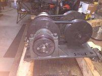
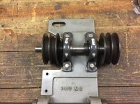
Tom Degenhart alerted me to a similar Worthington Drive available from Lost Creek Machine. They sent me a couple pictures of the one they have in stock. They have a model 4B if anyone is interested. It's a little different than the 3B in my previous pictures. The sheaves and bearing setup appears identical. The main difference is that it doesn't have the shaft and sprocket in the underside of the main plate. Apparently opening and closing the sheaves is controlled by another means.

Here are the pictures of the model 4B drive:

WP_20171127_09_39_41_Pro.jpg WP_20171127_09_39_32_Pro.jpg
 
Now you should publish an article about rebuilding the drive.

Tom

I did ask if anyone was interested in documentation over on the Sheldon Lathe Yahoo Group. There were absolutely no responses either positive or negative. Apparently there are so few lathes out there with this drive system there isn't much if any interest. Just in case, and for future reference I did take about 50 pictures in various stages of disassembly and assembly. Most of it was for the CYA factor.

Sometimes I get a project started and life takes a quick turn. In some cases it's taken me weeks and even months to get back to it. This time I got lucky, the process went smoothly, I didn't procrastinate, and there were no disasters on the home front. It only took a week from start to finish. That includes several hours cross referencing and ordering bearings. I believe it could be an all time record.


Back
Top