What's new
What's new

Simple Brooks Brushless 240v Single Phase Motor Wiring HELP!!!!

sapwood

Aluminum
Joined
Dec 7, 2013
Location
sunderland
can anyone help me wire up this motor? non of the wires are connected. ive included a rough sketch of what I have. basically two pairs of winding wires with two pairs of continuity and one set shows 10.3ohms resistance and the other 3.3ohms.
Their is also the capacitor, plus the centri switch and also a funny lookin plstic enclosure with two wires coming from it and its screwed within the back of the motor end plate. see pic
if anyone can explain to me the wiring, in laymans simplified lego terms as im no real electrician,
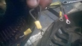
WP_20171114_016.jpg
WP_20171114_015.jpg
brooks.jpg
 
why not add something constructive, and if you read the past two threads this isn't the same motor or the other project.... idiot
 
why not add something constructive, and if you read the past two threads this isn't the same motor or the other project.... idiot

At least post it in the proper forum sub section.

Haven't you noticed your post's keep getting moved by the admin ?
 
no I havent budd, as im too busy trying to get projects finished instead of spending all my time like others reading folks posts and pulling them apart... I mean come off it, 83views and the only response is one sarcastic jackass, not one bit of help
 
no I havent budd, as im too busy trying to get projects finished instead of spending all my time like others reading folks posts and pulling them apart... I mean come off it, 83views and the only response is one sarcastic jackass, not one bit of help

Notice there is an "Electrical section"....

Note where some of your post's have been moved to ?

I'm trying to HELP you, but you just don't seem to understand.
 
can anyone help me wire up this motor? non of the wires are connected. ive included a rough sketch of what I have. basically two pairs of winding wires with two pairs of continuity and one set shows 10.3ohms resistance and the other 3.3ohms.
Their is also the capacitor, plus the centri switch and also a funny lookin plstic enclosure with two wires coming from it and its screwed within the back of the motor end plate. see pic
if anyone can explain to me the wiring, in laymans simplified lego terms as im no real electrician,
View attachment 212782
View attachment 212783
View attachment 212784


You will most likely get the infomation you are looking for from the Model Engineer group.


http://www.model-engineer.co.uk/forums/


They have a lot of similar questions, as a lot of home workshops are using old motors to get their machines up and running, so your problem would have come up several times.
 
can anyone help me wire up this motor? non of the wires are connected. ive included a rough sketch of what I have. basically two pairs of winding wires with two pairs of continuity and one set shows 10.3ohms resistance and the other 3.3ohms.
Their is also the capacitor, plus the centri switch and also a funny lookin plstic enclosure with two wires coming from it and its screwed within the back of the motor end plate. see pic
if anyone can explain to me the wiring, in laymans simplified lego terms as im no real electrician,

View attachment 212782
View attachment 212783
View attachment 212784
Main winding is usually lower ohms start is higher.Start winding is connected to start capacitor and centifugal switch.When motor starts power runs through both windings with the capacitor making the start winding pull the rotor until it is up to speed.When motor is up to run speed the centrifugal switch disconnects the start circuit.
 

Attachments

  • capacitor start.JPG
    capacitor start.JPG
    18.9 KB · Views: 5,501
can anyone help me wire up this motor? non of the wires are connected. ive included a rough sketch of what I have. basically two pairs of winding wires with two pairs of continuity and one set shows 10.3ohms resistance and the other 3.3ohms.
Their is also the capacitor, plus the centri switch and also a funny lookin plstic enclosure with two wires coming from it and its screwed within the back of the motor end plate. see pic
if anyone can explain to me the wiring, in laymans simplified lego terms as im no real electrician,
View attachment 212782
View attachment 212783
View attachment 212784
From what you describe the high resistance winding is the run winding and connects across the 240 volts. The low resistance winding is the start winding and it goes in series with the switch and capacitor. The string of those 3 items also goes across the 240. The order sequence you wire them in does not really matter unless one end of the start winding or centrifugal switch is already connected to somethig else. . The cap has no polarity so the terminals are interchangable. If it runs in the direction opposite of what you want, reverse the start winding connections. The extra little gizmo might be a thermal overload switch but I would be guessing. What I described should make it run if nothing is defective.

Sent from my SM-G900V using Tapatalk


Back
Top