What's new
What's new

Tapered plain bearing runout

Brian_Petersen

Plastic
Joined
Apr 20, 2017
Hi,

My name is Brian and I come from Denmark and have just registered. I have read a lot of different posts regarding the issue I have, but it's not quite the same problem.

I have just bought an older MAHO MH 600 manual milling machine (from the 60's I guess). The price was really good, so I drove for 15 min. and made a quick inspection and bought it after been having a good conversation with the previous owner. I asked for the spindle runout and he mentioned that he had just replaced the bearings and he also showed me some nice looking gears he had just made, so all seemed good.

After a few days when I got on to do some serious inspection, I was disappointed to see that the runout was around 0.07 mm or 0.0028 in! The manual says 0.005 mm or 0.0002 in is acceptable.

I then disassembled the whole spindle and found that it had a tapered bronze plain bearing in the lower part and two thrust bearings in the upper part of the housing. The two thrust bearings are located on both sides of a positive stop and thereby constraining the journal axially.

With this knowledge, I guessed that the taper was i bit worn and shimmed the lower thrust bearing, so that the tapered journal would register better into the tapered bronze bearing. I ended up shimming it 0.09 mm or 0.0035 in.

I got the runout down to about 0.04 mm or 0.0016 in, but the journal then began to drag on one or two spots.

My fear is that the lubrication of the bronze bearing was neglected and it all got very warm, maybe bending the journal. I don't know if this is a right assumption, but it seems plausible.

I have tried to place the journal in two V-blocks, but the tapered end gets me into trouble making runout measurements.


Please help me with some guidance on how to take the necessary steps and in the best order, to deal with this problem.

PS: Is it correct that the runout will be better doing a actual job, because the journal somewhat self-aligns on the oil film?


Regards,

Brian.
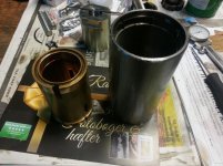
20170405_192409.jpg20170405_173528.jpg20170404_190557.jpg20170326_202428.jpg
 
Last edited:
"replaced the bearings"

I would imagine you have to assume ignorance prevailed and the SKF thrust bearings are not the original precision class
 
The journal / thrust bearing assembly has been shimmed upwards into the tapered plain bearing by 0.09 mm or 0.0035 in as I wrote, by adding shims to the positive stop. Whatever precisionclass it is, I think that no bearing would be this much off in height. The preload is done by the nut that is screwed onto the journal with the constrained bearings in between.
 
The journal / thrust bearing assembly has been shimmed upwards into the tapered plain bearing by 0.09 mm or 0.0035 in as I wrote, by adding shims to the positive stop. Whatever precisionclass it is, I think that no bearing would be this much off in height. The preload is done by the nut that is screwed onto the journal with the constrained bearings in between.

Precision class controls run out of assembled bearing, and on this thrust bearing, that would certainly be axial
 
Sounds like you guys are missing the "tapered plain bearing" part of the equation. Basically a finely fitted tapered bushing with large surface area. The original installer must have left it too loose, so OP tightened it up and got a bit less runout. Probably similar to a Mattison surface grinder spindle. I sincerely hope that the tapered plain bearing isn't what got replaced by the DIY guy. They need to be scraped for fit and bearing. If that's what he replaced, it sounds like he didn't do that part of the job, leaving the OP in a bit of a pickle. I'd say maybe it's time to get in touch with the seller and find out exactly what he did.

The runout should be chiefly based on concentricity of the tapered journal to the spindle bore, but the thrust bearings could certainly affect it somewhat. I would be very surprised if they could throw it out as much as the OP states though, considering the shaft would need to be running out quite a lot at the opposite end to get nearly .003" runout at the spindle bore end.

It's also possible that the spindle was put into a bind/warp when the thrust bearing nut was tightened if the bearings have a bit of distance between them. I'd place the spindle with thrust bearings assembled in v-blocks or between centers and check runout at a few different places. If the spindle has a slight runout it may be possible to tweak it a bit by tapping the bearing spacer or similar - I've done this with Bridgeport spindles to get runout dialed in near perfectly, not familiar with the Maho - it may not be possible there depending on spindle configuration and diameter, thrust bearing and spacer configuration etc.
 
Hi eKretz, you understand what is going on here.

I'll try to put the journal between centers and check the runout and let you guys know the values.
 
Plain bearings are just dumb holes, they don't cause any runout so long as they are accurately round. If they are egged, then you've got freedom of movement possible in the longer axis of egginess. A bit of testing with bluing should determine if you've got reasonable contact with points at several locations (with the spindle set in extra tight for this test only).
However an old mill that runs on plain bearings isn't going to be any sort of a high speed darling, kind of sad to put a bunch of effort into an old mule like that.
 
I would think that the runout is controlled by the fit between the tapered plain bearing and the tapered journal?

John wasn't just guessing.

Of value for you to do more reading and seeking of understanding. Doesn't cost much.

That was not a guess, either.

Calculating oil film for various material, loads, and speeds was covered in - IIRC - a first-year ME course when I was at Uni. Long time ago now. Very.

Good news is that these days there is probably a calculation toolset on the internet that Google will find for you. It will want several inputs.

That said, there is not a great deal wrong with following the maker's recommendations.

As to how good you can expect to make it? Expect limited gains.

Tapered plain bearings are not hard to do well. However.. as stuff gets warmer?

It moves. That matters.

All the skill and patience in the world can only do but so much about that before the Laws of Physics remind you why we call them "Laws".
 
Iv'e got an idea of remachining the journal outside taper and fit it with a matching bushing. Then machine some steps into the outside of the bushing and install deep groove or roller bearings on it. Next I will need to make a new housing (currently the bronze part) for the journal assembly and install all that into the spindle housing. Some work to be done, but it will take a lot of the guesswork out for the years to come + its nearly maintenance free. Do you guys like that idea?
 
Iv'e got an idea of remachining the journal outside taper and fit it with a matching bushing. Then machine some steps into the outside of the bushing and install deep groove or roller bearings on it. Next I will need to make a new housing (currently the bronze part) for the journal assembly and install all that into the spindle housing. Some work to be done, but it will take a lot of the guesswork out for the years to come + its nearly maintenance free. Do you guys like that idea?

I wondered how long before that idea showed up!

Pro:

You can enable speeds clear up to 6,000 RPM "cheaply" [1] - way more than the plain bearings would be comfortable with. OTOH, it is only a mill.

Con:

Plain tapered bearings are legendary for standing up to heavy loads, lower-RPM pounding and abuse. That is why they were installed.

They are already "paid for".

There is no delay while you do conversion calculations, then machining, possibly also corrections or do-overs.

There is near-zero risk of f*****g it up if you just run whatcha got.

And then.. "why"? What is to be gained?

You have lower TIR already than many mills.

Higher speeds for Carbide deeds I can dig. But the cost of the uber-precision roller bearings to get there?

Best to already be on a gurney and IV drip before you hear the price!

"ABEC 9" (the company name, not the classification) skateboard bearings just will not do! Bearings that CAN do should be NEW, and from a trusted source, not 'mystery' salvage off eBay, some other continent.

:D

[1] Where "cheaply" is maybe $3,000, US, 50 millionths runout-minus super-precision toolroom lathe as an example. That does NOT get one into "HSM" and 20 kRPM + spindles, though. Not even close.
 
Id keep the taper bearing.

Id find some way to check the spindle out of the machine to make sure youre good that way first. How were you measuring this runout btw? Could be that the spindles a bit beat up etc. Scraping the bearing for fit should be easy enough.
Re the thrust bearings. Would imagine theyd have to be impossibly horrible to be causing that much runout. I remember watching a video of bearing replacement on some thumping great machine. The guy doing the spindle repair was talking about a big set of Timken rollers and mentioned what a Timken bod had told him. The only difference between a standard and P bearing was inspection. They all came off the same batch. Worth thinking on before you drop a pile o dosh on P bearings.
If you get all your eggs lined up, one step one step check check check, you cant not have a result at the end of the job. Enjoy the learning ;)
 
How did you measure the runout? Is there any movement between the spindle and bearing? Do you know for sure that the tooling hole is absolutely concentric with the bearing journal? That is what I suspect. Assemble the quill and hold it securely, set up a dial indicator on the taper and check the run out. If the spindle is not loose in the bearing the run out has to be encentricity between the bearing journal and the ID taper for the tooling. I see no point in redesigning the wheel here, even if you are successful with the bearing conversion so what? The rest of the machine is designed around the spindle, you will not be able to use the higher rpm spindle without risking damage in other areas.
 
I have now blued the journal and turned it a few times, with no other axial force than gravity pressing the bronze bearing onto the journal. First I applied a very thin layer, but nothing showed up. Next, a bit more generous amount. Bronze bearing at 0 and 180°.

IMG_0028.jpgIMG_0030.jpgIMG_0032.jpg
 
How did you measure the runout?

I'm curious also. I have a Timken 2794, a very common bearing, and it has a 2720 race.

I just used a noga holder with a .0005" dial indicator against the outside race (new bearing). It's between .00025" and .0005"

This bearing is 2.875" dia,

Can take a static load of 23,000 flbs.

These bearings were used in the Chrysler Imperial, the largest in the Chrysler line in it's day... I bought the bearing on ebay for $2.99 (shipping was $4.99), and the race was $11. It's gonna be a radius turner, for lack of a better project at the moment.

To test a bearing properly you would need to place a static load on it when measuring the runout. I'm not sure how you would do that.
 
How did you measure the runout? Is there any movement between the spindle and bearing? Do you know for sure that the tooling hole is absolutely concentric with the bearing journal? That is what I suspect. Assemble the quill and hold it securely, set up a dial indicator on the taper and check the run out. If the spindle is not loose in the bearing the run out has to be encentricity between the bearing journal and the ID taper for the tooling. I see no point in redesigning the wheel here, even if you are successful with the bearing conversion so what? The rest of the machine is designed around the spindle, you will not be able to use the higher rpm spindle without risking damage in other areas.

The runout was measured on the inside of the taper of the journal. Not to be confused with the bearing tapers. I was also able to rock the journal back and forth by a measurable amount.
 
Plain bearings are just dumb holes, they don't cause any runout so long as they are accurately round. If they are egged, then you've got freedom of movement possible in the longer axis of egginess. A bit of testing with bluing should determine if you've got reasonable contact with points at several locations (with the spindle set in extra tight for this test only).
However an old mill that runs on plain bearings isn't going to be any sort of a high speed darling, kind of sad to put a bunch of effort into an old mule like that.

What Hu said.

Tell us about how you measured your runout. I suspect you are using the term runout when you mean free movement. They are two very different situations, and are sometimes confused by people who are native English speakers. Add in translation problems and it gets more confusing.

On edit: You replied while I was typing.

You can't measure runout of a tapered surface that is subject to axial movement. Your situation is even worse, with both inside and outside tapers. This brings us back to two previous posts. Johnodor's about the precision of the thrust bearings and Hu's about bushings are dumb holes. A poor class of precision thrust bearings (or poor installation) will cam the spindle in and out, showing runout as you measure it. If you are just turning the spindle, you are measuring runout in the spindle itself, not the bushing, unless something else is happening.
 
I testet the runout by applying some light oil to the tapers, without any thrust ball bearing installed. The two things were only held together by gravity. TIR was 0.016 mm / 0.00063 in!

IMG_0033.jpg


Back
Top