What's new
What's new

Have I set this job up right? Milling keyways and drive lug slots on arbor.

stoneaxe

Stainless
Joined
Mar 2, 2010
Location
pacific northwest
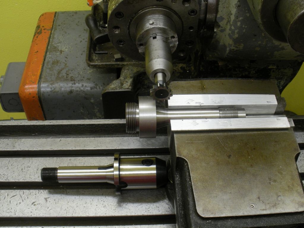
This is a shank/arbor for a boring head to VN 12 taper. I need to cut a keyway, and then two drive lug slots. A end mill holder with the desired features is shown laying on the mill table.

This is simple stuff for you guys, but bear with me- I do not know yet when my set ups are "good enough", "way overkill" or "destined for disaster"! :D

The arbor is set on parallels and clamped with aluminum pads. It is clamped offset in the vise jaws- do I need to use a spacer block on the open end of the vise jaws? Seems like it would be a good idea...at least it is shown as standard practice in the books. Or is there enough engagement?

How do I find exact centerline of the cut? So far, I have used a square on the mill table, and measured from the vertical leg set to bear on the arbor OD, to the cutter. This shows about .002 out, but I am not happy with the measuring-I am using a dig.caliper and it is difficult to hold it accurately to span between the square and the cutter.

After this cut, I will need to mill two 1/2" drive lug slots 180 degrees apart, and 90 degrees from the key slot. Indexing these cuts accurately is my next question- How?

5c75882a-33f0-446a-afd7-a5363b480796_zps03d40605.jpg
 
Thinking back to my "Quartet" days, the way I would center this part is to touch off the tool using a sheet of paper between the cutter and the part. Hold the paper with one hand and sneek up on it with the cross feed handle. once the cutter catches the paper and pulls it away from your fingers you should be within a couple thousanths. Measure your diameter where your touching off and take half of that, add half the width of the cutter, plus a thousanths for the paper and you should be right on center.
You dont need a spacer block if your using a good milling vise either. How you have it clamped should do fine as long as the vise is in good working condition.

For the two keyways 180 apart, find center using the same meathod. Once you have the first keyway milled, loosen the vise and flip the part over and set it down squarely on the slot in the bottom of the vise. If you do it correctly it will be 180 away from your first cut.

Since it dont look like you have ample clamping area doing it that way, a super spacer or collet block would be a great help.
 
I'm no expert on finding the CL on the shaft - one way would be to mic the cutter, mic the od of the part, then bring the cutter outside of the diameter (run the part away from the cutter if that makes sense) then mic over the OD of the part and the cutter, it does not need to touch the outside of the dia. Now appropriate subtraction will get you to the CL.

To index 180 degrees - one way if you have a square or hex collet block and the shaft will fit into a collet its simple. If you don't have that mount it vertical and do one side then the other (thinking vert mill). In a Van Norman set for horiz - turn the vise 90 deg and again one side then the other without moving the part from the vise.

I'm sure others with more experience and more tricks will comment as well.
Paul
 
It might be kind of cool if you stood it up vertical on the table and then you could cut both sides of the part in one op. It would automatically be dead nuts and that way you would't have to be a good machinist to get it perfect.;)

Maybe you could pull in your cutter a little so it's not sticking out so far. Always shoot for maximum rigidity. Your cutter is already sticking out 14 miles with that long tool holder.
 
Abom has the way to get on center. I just run a stationary cutter up to the work with a slip of paper held between until I feel a slight tug on the paper when slding it past the cutter. A sheet of notebook paper is .003 thick. Measure diameter of the part where you touch off. Move half the width of the cutter plus .003, center of cutter is now on the edge of the work. Now, move half diameter of the work and you are centered.

Vise is a tough way to go about this. As you point out yourself, the back end of the jaws are unloaded, so it's going to cause the work to crawl on you. I'd put the large diam in a T slot on the table, then block up the back end until it is level and clamp directly to the table.

Now, John has a good idea about doing both sides at once, but you need not stand it vertically. This is a VN. You can just lay it on the table perpendicular to the way it is now (swivel vise would be super easy to just crank around and square up), then go at it with an endmill, horizontally. Alternately, you will have to do as Abom says and flip the cutter 180 degrees or use some kind of index fixture. I'd be using my 5C spin index for this one.

All that said, this being a boring head, it is not subject to heavy loads, so my approach would be to put the woodruff key seat in and then remove the drive lugs from the spindle nose when you need to use it, instead of over thinking this. (On edit, I notice you don't even have the drive lugs installed, so that is definitely how I would go at this.)
 
Went out and tried to center the arbor using the paper, and two 1/2 diameters- was no closer than using the square on each side, then remembered I had to subtract the paper thickness- duh!
I will beef up the clamping, and really like the idea of just milling from each side- like the old VN literature says, move the tool, keep the part fixed.....
I will mill the drive lugs, not because it needs them but because I need all the experience I can get- this is training for a newbie.
 
I would get rid of the vise, and go with the suggested vee-block method. To index, blue the big end after clamping down; then scribe a vertical line on face of piece as a reference line (need NOT to be on center of work). Cut first drive slot, then roll over, using previously scribed line for positioning. Be sure to locate line using same square, in same orientation, as was used to originally draw the line. Even if the slots might be a smidge off the theoretical CL, they will still be 180 from each other, and will work ok.

If the thing is stood on end and double-milled with the slots a smidge off center, the indexing error will be magnified by two.

GO VAN NORMAN.
 
I would agree with putting it on the table or in a v block. if you orient the part as you have it in the vise you could mill with your woodruff, then change to your endmill and do the drive slot facing the spindle in the same setup, rotate the part and install a key into the slot you just milled and indicate the key, mill you other slot. Done!
 
I definately would put a jack under the end sticking out of the vise with a small clamp on it. Any pressure from your cutter is going to push it down no matter how much pressure the vise jaws are holding it by.
I agree with the rest of the people on here using a piece of lens tissue is what I use to touch off the side of the part. Then take half the cutter and half the part dia. and move machine table in that amount.
I would of tried to hold it in my space/rotary table in vertical position to do it that way the spacing would be accurate.
 
So long as the cutter is in good shape (square and corners not rounded) it can be used to find its own center on a round by noting when it starts cutting a corner.

eyeball the cutter as near as center as you can. Raise the table or start into a taper carefully until the cutter just raises a side, on one side. Move the table in that direction (so the cutter cuts over the side it just raised). cut forward again raising the table until the cutter raises a side again, etc. Once the cutter raises both sides at the same time, you are on center. Lock things down and make the cut.

I usually do that, but being a worry wart, then sometimes use a planer gage or adjustable parallel to each side of the vise (Kurt) to make sure the distance is the same.

If this is done carefully but "expeditiously", all initial test cuts will be obliterated by the correct cut. If the apparently correct cut needs moved a couple thou or so after gaging with an adjustable parallel, that evidence with be removed when the key way is de-burred.

Agree with the jack or adjustable height center into the end for support.

To cut the drive slots, if you have a couple substantial Vee-blocks, you can clamp them to it and flip side to side (or end to end against some angle blocks clamped to the table) to do opposite sides but it will be necessary to clamp them over parallels to clear the Vee-block clamps, depending on the style. Just don't scrimp on support and clamps to the work and to the table.

smt
 
The trouble I personally would have with the setup as shown in the photos, is that
the moment the cutter touches off on the sharp corner it is near, it will grab and
tend to push the larger diameter, overhung part down and lift the shank of the
arbor out of the vise.

This is for me a statement that first off, the shank is never exactly constant diameter
so it is held only for a portion of its length in the jaws, and also that a round part
in flat jaws is only held via two line contacts even when the geometry is perfect.

So I would double down on the comments above to fixture it up another way, the
v-block idea is excellent. If there were a way to do it between solid centers that's
nice as well.

If you go ahead this way then go real easy on the start of the cut as I've found if
the setup is marginal like this, as long as the very first cut where it tends to grab
the corner goes ok, you can nurse it along. If you were to replace the full-width
cutter with one that is narrower, and take two or three cuts to get full width, that
would also reduce the chances of a part tear-out.
 
Things I have learned from this thread. First, there are a bunch of folks out there who are willing to help my online apprentice program-- thank you all, I really appreciate it!

There is no such thing as "clamped too securely". One would think I should know this already, after applying so many woodworking clamps to a glueup that I could not lift the assembly..!!:D

Instead of measuring twice and cutting once, as in woodworking, it is measure seventeen times.......then recheck the clamps.....!

There are at least three methods to do any operation, per machinist-- Two of these methods can be used by other machinists as well, but the secret "third way" must be learned in remote Tibetan monasteries.

So far I have replaced my aluminum vise pads with better aluminum pads, used a spacer block on the open end of the vise (another arbor turned to the same diameter) , and contemplated the mysteries of the "vee" block, of which I have two, secreted in a corner of my tool box, emitting mysterious yet harmonious emanations.
These "vee" blocks the masters speak of- the shaft is to be held to said vee block with the supplied vee block clamp, and then the whole arrangement clamped to the table with standard tee slot bolts and bars?
This offers another benefit, as the main reason the cutter extends 14 miles from the cutterhead spindle is to clear the vise, as shown.

I will work on my clamping setup- but now,another question-

A SFM of 50 to 70 is indicated in the books for a HSS cutter on this type of steel -1144 (I think). The VN has 175 rpm and 270 rpm to choose from- that is 45 sfm and 71 sfm respectively. The cutter is 1" diameter , 12 tooth and will be hand fed. Which speed you you choose? Is the faster speed more likely to chatter?
 
More likely to chatter and also likely to burn up the tips of the tool. Start slow and work up. Only thing running slow will cause is a few more minutes of time to finish the job. If it was a common cheap endmill, I'd say go for 270, but this is a fairly expensive cutter and one I'm sure you plan on using again in the future to put the little pocket in your home made VN tooling. Run very conservative. I doubt you'll have any chatter issues with this cutter in a VN 12.

BTW, if you use the powerfeed, calculate a chipload for your cutter. Chipload x teeth on cutter is fed in "/rev. "/rev times rpm is "/minute of feed. A chipload of .001 on a 12 tooth cutter is .012 per rev, at 45rpm that is .54"/min feed, or close to 1/2"/min as you can get. Again, slightly less is better in this situation.
 
you could also mill the first slot out, clamped securely how ever you're going to - then flip it over and set it on a piece of keystock to accurately align for your next cut, 180 degrees opposite. That way you're locating off the cut and not setting it down on edges that may have a slight burr or have been deburred the slightest bit unevenly.
 
The vee-blocks for shaft work are NOT the fancy dan B&S or Starrett jobs with the fragile yoke and set screw, but keyed-on-the-bottom blocks that are placed into the milling machine t-slots for supporting shafts parallel to the machine table. Such sets can be purchased (or made) from small to rather huge. Clamping of the work down to the mounting blocks is through the use of t-nuts, studs, straps, step blocks, and the like, and limited only by one's imagination. Sometimes it can be rather tricky, especially on smaller things, to both secure a piece safely, and still be able to approach the work freely with the cutter. Do not get discouraged, as this stuff is not learned in a day nor does anyone know it all. Hardly does a day go by that I do not ask myself why I had not thought of this neat trick twenty or thirty years ago.
 
Hmm- that makes sense- it would be pretty easy to make a vee block set with a ridge on the bottom to correspond to the table slots, and a couple of hole drilled through for a bolt to to engage a tee slot nut. Even the ridge could be inlet into the bottom of the v block so it could be removed if necessary to turn the block at an angle... sounds like a fun project.

Anyone care to give me a tutorial on machinist jacks? I see these little things that look like a miniature house jack, but how are they secured? Just by compression between part and table?
Would it make sense to make them with a base that could be bolted to the mill table? It seems like they would be tricky to use otherwise, as if they are tightened too much they could push the part out of alignment, and if they are not quite tight enough they could vibrate loose.
 
I think I wouldn't be so quick to dismiss standard V blocks. I have not heard of the other kind, and would like to see a picture.

V-blocks come in a lot of different sizes. You would need ones that held the shaft so that it's diameter wasn't larger that the depth of the block.
That way. The v-block holds the shaft with the yoke preventing lift out, and the vise holds the V-blocks (preferably two of those).

good luck,

Jon P.
 
Anyone care to give me a tutorial on machinist jacks? I see these little things that look like a miniature house jack, but how are they secured? Just by compression between part and table?
Yup. They can also be used horizontally or vertically to reinforce thin walls or flanges that would be distorted by clamping pressures.
Would it make sense to make them with a base that could be bolted to the mill table? It seems like they would be tricky to use otherwise, as if they are tightened too much they could push the part out of alignment, and if they are not quite tight enough they could vibrate loose.
I've seen some shop-made sets with bases like that, especially for heavy (boring mill) work.

In most cases, you should think of the jacks like adjustable parallels or rest buttons. You don't actively clamp with them, you just take up (exactly the right amount) of slack and provide a compression member for clamps to (indirectly) bear on.

Edit: This reminds me of a job I did recently. A short turned piece with 1.308" diameter 0.5" long stud on one end, 1.5" diameter flange 0.25" long, and 1.06" diameter 1.5" long stud on the other. I had to mill a flat on the 1.06" diameter stud almost all the way to the flange. I used a pair of small v-blocks to support the two studs, with a pair of adjustable parallels bringing one v-block up to the right height. (A really good reason to have more than one set of adjustable parallels, by the way.) The part was clamped conventionally on the larger stud. The v-block on parallels, supporting the smaller stud, was clamped to the mill table, but the stud just rested on top of it. The relevant point is that the adjustable parallels were not used to actively clamp, just hold things rigidly at the right level. Jacks usually work the same way.
 
No need for keys on the V blocks. In fact, I wouldn't want keys on them, as it limits you to using them in one direction only. Lightly clamp the work approximately in line and then indicate the work square with gentle bumps, just like a vise jaw, then clamp securely and check to make sure it is square before starting to cut.

I often use clamp kit components to make up jacks. You can use clamp nus and studs, combined with coupling nuts and make all kinds of lengths of jacks for special stuff. I have also used just standard bolts and nuts in some situations. I use the bolt and nut trick every few weeks when turning a special roll we plate for a manufacturer of textile film production equipment. The roll is supported only by a thick flange in the middle on a arbor, which leaves an otherwise unsupported 9-16" diameter 1/2" thick tube that will ring like a bell when you start working it. Tolerance is tight and the cut very light so there's no second chances. I just lightly run an opposing pair of bolt/nut jacks between the ID of the outer shell and the arbor on both ends. No ringing.


Back
Top