magno_grail
Hot Rolled
- Joined
- May 29, 2014
- Location
- ca, US
Hi All,
First posting. I bought the VF1 with a few known issues and several unknown ones. I think the last time it was cleaned was '91? It appears to have been maintained by a shade tree mechanic. There were several parameters changed or disabled. I took out 5 gallons of steel slivers stuck to the inside of the cabinet and under the way covers. They were using oil instead of coolant which stuck the slivers everywhere. The oil did not keep the underside of the way covers from rusting or the ends of the ways that were rarely used. I bought one of the China Freight electric pressure washers to blast everything. It works fine, no problems and has saved a lot of time.
Anyway, first problem was the screen, too dim to read except in the dark. It also had been replaced at some point and another chassis was bolted in place. I took the CRT out of a Digital VT220 and replaced it with that. Now it is readable but there are lines on the left from the beam wraping to the next line. For now I will change out the CRT driver board with the VT220 board which I am sure is a better quality. When I have more time I will make an LCD replacement.
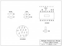
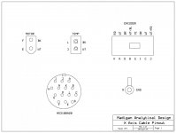
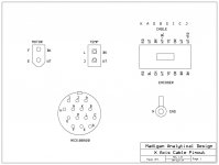
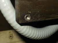
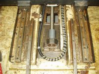
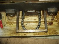
The Y axis had an intermittant over current (known issue). When jogged at 0.01 the Y alarmed out but ran fine at slower speeds. The X axis did not run at all with an over current alarm (unknown issue). I pulled the servos and found the inside of the brush caps packed with carbon. Whoever rebuilt the Y servo did not put the O-rings back in so there was oil inside the servo. The X cable casing was broken in three places between the table and the back of the cabinet. I cleaned the carbon out with brake cleaner. The brushes were fine. It still had the same problems and I could see sparking in the brush area through the wire hole. I was quoted $750 as a start for a rebuild. Seems a bit steep for a simple DC motor. I went back in and cleaned between the commutators of the Y servo and thoroughly washed down the armature and commutator with brake cleaner ($2.99). Now the motor worked without alarming. I put the Y servo on the X cable and it works, so the wires are fine, I just need a new casing.
Doing the same with the X servo did not produce the same results. I found inside the cap that one of the brush holders had crumbled near the wire connection, probably from the heat of arcing due to the carbon. The servo still over current alarmed. I then checked the resistance between the motor wires and the case, 350 Ohms. Taking out the brushes one by one I found two opposite brushes were the problem. These were connected together and one was the crumbled holder. To determine if it was the armature or the brush cap I measured between the brush holders and the case. The holder was the problem. I tried replacing the brush cap with the one off the Y servo and the motor worked fine. So I have to get another cap or holder. I presume these are glued in place?
The door on the ATC was held open with a piece of cardboard wedged under it (unknown issue). The pin that moves the door is missing. The original was just a steel pin, fortunately I have a 1/2" cam track bearing so I only need a bracket to mount it. I will add the nylon buttons to the door as a bearing slide. One door on the tool holder is stuck open. I have to take off the cover to see if it is just chips or something else. The tool changer has some slop on the V rails. Both the eccentric adjusters are fully in. The post that holds the upper right V bearing was broken off and replaced with a piece of bar stock. Both the ways have wear, especially at the ends of the stroke so they will likely need replacement. The cable casing is broken. Has anyone used the high flex casing from McMaster? It may be more durable than the Carflex.
I could not get the spindle to orient, the tool release or high gear to work (unknown issue). I had 80 PSI at the compressor. The manifold block behind the spindle motor was hanging by the copper lines from the gear changer. I made a mount for the solenoids and attached it to the flex conduit holder. After cleaning the air actuators and increasing the pressure 90 PSI the tool release and spindle lock worked but the gear changer did not. I put 110 volts AC on the solenoid and the air actuator worked. Measuring the low and high signal at the connector and got nothing. I tried measuring the voltage across the low and high gear LEDs on the I/O board and still nothing. I am still not sure if it is a parameter that I have not found or a problem upstream of the I/O board. A friend said it could be one of the high/low switches are stuck. I will have to go back and move the air actuator using 110AC at the plug and see if the switches read it.
The top cover is split at centre front. It has a piece of aluminum plate bolted across the split. I will have to come up with a more secure re-enforcement. I noticed on the '91 VF1 rebuild posting there are two brackets with a short 45° at one end. I do not have these. Are these supports for the sides at the bottom or top? The lower corners at the rear do not fit very well so I am wondering if the cabinet is sagging. The operator light was hanging by the wires. For now I will replace it with an automotive fog light that I have.
That is it for now.


