Eric U
Hot Rolled
- Joined
- Feb 26, 2003
- Location
- Eastern AL
I am.
On my last 20 part run, I got real tired of the tool change routine: change tool, turn on coolant, adjust loc-line, hit green button, repeat. Sometimes in the adjust the loc-line stage the loc-line would pop off the ball-valve and spray coolant all over the ceiling and in my face. This latest fight with the loc-line reminded me of how much I hated it all the times before. I started thinking of ways around it.
A few weeks ago I had back surgery. I spent A LOT of time in bed and on my couch. I started sketching what a repeatable and easy to use coolant setup would look like. OK, the Dorian Victory toolpost with their Jet-Stream tool holders would be nice, but I didn't have that and wasn't planning on changing over. Anyway, the limited choice of toolholders and high prices are what kept me away from them in the first place back when I bought my TL-1.
After I decided on a design, I drew it up in Solidworks and ordered parts. Finally I got well enough to venture out to the shop and I whacked out enough parts for two TL coolant "kits". One for me, and one for PM member John Deere. I test drove mine and it worked great. At first look it appears to be vastly better than adjusting the loc-line. I haven't done a production run (back can't handle it yet), so I don't know if some irritating little gremlin might pop up. I did find one thing I would change if I were to do it again (but probably won't).
What I wanted to accomplish was to attach a part to each tool holder that has a way to get coolant repeatably on the insert and is easy to attach to the coolant line. I decided to attach this part to the toolholder by replacing one of the stick tool clamp set screws with a longer one and by using a washer and nut. I've only got Aloris and Dorian tool holders, so I designed this coolant block to fit either holder. The set screw spacing and distance from the edge of tool holder is slightly different between the two brands. This coolant block has a small 0.1" step in it to keep it from rotating when attaching/removing the coolant line. I made my stuff to fit Aloris and Dorian CXA-1 and -2 tool holders and other holders that have similar set screw spacing. I don't know if it will fit aftermarket tool holders or other sizes.
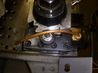
The coolant line is attached to this coolant block through the use of a mini quick-disconnect like is used on air systems. A quick-disconnect fitting is on the back side of the block and a compression fitting on the front. I used 3/16" copper refrigerator line to get the coolant from the compression fitting to the insert. I decided on the more expensive mini quick-disconnect instead of regular sized ones for three reasons: I could make my block smaller because of the smaller fittings, the smaller fittings stick out of the back side of the tool holder less, and the smaller diameter quick-disconnect (5/8") will stick out to the side less than the full sized ones.
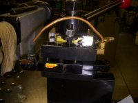
To get the coolant from the coolant tank to the quick disconnect, I decided to run it through a manifold. After I took apart all the claptrap that was the coolant bracket that Haas sent me, I found that the line from the coolant tank terminated in a 1/4-18 NPT fitting. I had that fitting run into the side of my manifold block and come out the top of the block straight into a ball valve and then to a 3/16" hose barb. That is where the hose connects between the quick disconnect and the manifold. Next to the ball valve/hose barb on the top of the manifold I put another mini quick-disconnect fitting and had a hole run through the manifold that connects it to where I screwed in the dreaded loc-line (also 1/4-18 NPT). That way if there is no way to hook up a doo-dad on the tool holder to get coolant to the tool, just plug the quick-disconnect back into the manifold and use the darn loc-line. This is where I would change my design some. I would have the quick-disconnect fitting come in from the operator side of the manifold instead of the top. It would make machining the manifold simpler and would make it easier to connect. I was worried about clearance attaching from the side, but I'm not anymore.
For through-coolant tools, I just make connectors that I can screw one of the quick disconnect fittings into and attach to the tool. In the pictures I show one of my through-coolant boring bars with a delrin connector. I just pipe tapped one end and bored the other end to fit over the end of the boring bar and glued it onto the boring bar.
Hopefully the pictures will clear up what I'm trying to describe.
Caveats: the coolant block sticks out the side of the tool holder by 1/2", and the mini quick disconnect by a little more than that. Be careful of working close to the chuck on large diameter parts as clearance could become an issue. The second possible problem is that I don't know what long-term affect the coolant will have on the o-ring in the quick disconnect as they are meant for air.
Total cost to put together a 12-part kit would be close to $100, not counting machine time. Cost per part is obviously lower the more you make. Some things I bought in quantity (like 100 2" 3/8-16 set screws) so my cost may be lower on some parts than you may be able to get if buying less.
I have no desire to make these for sale. I have more to do than I have time for. If anyone wants a BOM and/or drawings send me a PM. If there is a lot of interest, I could probably just post them here. Of course I could be way off base here. Maybe I'm the only one to have problems with the loc-line...
Eric U
On my last 20 part run, I got real tired of the tool change routine: change tool, turn on coolant, adjust loc-line, hit green button, repeat. Sometimes in the adjust the loc-line stage the loc-line would pop off the ball-valve and spray coolant all over the ceiling and in my face. This latest fight with the loc-line reminded me of how much I hated it all the times before. I started thinking of ways around it.
A few weeks ago I had back surgery. I spent A LOT of time in bed and on my couch. I started sketching what a repeatable and easy to use coolant setup would look like. OK, the Dorian Victory toolpost with their Jet-Stream tool holders would be nice, but I didn't have that and wasn't planning on changing over. Anyway, the limited choice of toolholders and high prices are what kept me away from them in the first place back when I bought my TL-1.
After I decided on a design, I drew it up in Solidworks and ordered parts. Finally I got well enough to venture out to the shop and I whacked out enough parts for two TL coolant "kits". One for me, and one for PM member John Deere. I test drove mine and it worked great. At first look it appears to be vastly better than adjusting the loc-line. I haven't done a production run (back can't handle it yet), so I don't know if some irritating little gremlin might pop up. I did find one thing I would change if I were to do it again (but probably won't).
What I wanted to accomplish was to attach a part to each tool holder that has a way to get coolant repeatably on the insert and is easy to attach to the coolant line. I decided to attach this part to the toolholder by replacing one of the stick tool clamp set screws with a longer one and by using a washer and nut. I've only got Aloris and Dorian tool holders, so I designed this coolant block to fit either holder. The set screw spacing and distance from the edge of tool holder is slightly different between the two brands. This coolant block has a small 0.1" step in it to keep it from rotating when attaching/removing the coolant line. I made my stuff to fit Aloris and Dorian CXA-1 and -2 tool holders and other holders that have similar set screw spacing. I don't know if it will fit aftermarket tool holders or other sizes.
The coolant line is attached to this coolant block through the use of a mini quick-disconnect like is used on air systems. A quick-disconnect fitting is on the back side of the block and a compression fitting on the front. I used 3/16" copper refrigerator line to get the coolant from the compression fitting to the insert. I decided on the more expensive mini quick-disconnect instead of regular sized ones for three reasons: I could make my block smaller because of the smaller fittings, the smaller fittings stick out of the back side of the tool holder less, and the smaller diameter quick-disconnect (5/8") will stick out to the side less than the full sized ones.
To get the coolant from the coolant tank to the quick disconnect, I decided to run it through a manifold. After I took apart all the claptrap that was the coolant bracket that Haas sent me, I found that the line from the coolant tank terminated in a 1/4-18 NPT fitting. I had that fitting run into the side of my manifold block and come out the top of the block straight into a ball valve and then to a 3/16" hose barb. That is where the hose connects between the quick disconnect and the manifold. Next to the ball valve/hose barb on the top of the manifold I put another mini quick-disconnect fitting and had a hole run through the manifold that connects it to where I screwed in the dreaded loc-line (also 1/4-18 NPT). That way if there is no way to hook up a doo-dad on the tool holder to get coolant to the tool, just plug the quick-disconnect back into the manifold and use the darn loc-line. This is where I would change my design some. I would have the quick-disconnect fitting come in from the operator side of the manifold instead of the top. It would make machining the manifold simpler and would make it easier to connect. I was worried about clearance attaching from the side, but I'm not anymore.
For through-coolant tools, I just make connectors that I can screw one of the quick disconnect fittings into and attach to the tool. In the pictures I show one of my through-coolant boring bars with a delrin connector. I just pipe tapped one end and bored the other end to fit over the end of the boring bar and glued it onto the boring bar.
Hopefully the pictures will clear up what I'm trying to describe.
Caveats: the coolant block sticks out the side of the tool holder by 1/2", and the mini quick disconnect by a little more than that. Be careful of working close to the chuck on large diameter parts as clearance could become an issue. The second possible problem is that I don't know what long-term affect the coolant will have on the o-ring in the quick disconnect as they are meant for air.
Total cost to put together a 12-part kit would be close to $100, not counting machine time. Cost per part is obviously lower the more you make. Some things I bought in quantity (like 100 2" 3/8-16 set screws) so my cost may be lower on some parts than you may be able to get if buying less.
I have no desire to make these for sale. I have more to do than I have time for. If anyone wants a BOM and/or drawings send me a PM. If there is a lot of interest, I could probably just post them here. Of course I could be way off base here. Maybe I'm the only one to have problems with the loc-line...
Eric U
Attachments


Last edited:
")


")


