What's new
What's new

VF-1 Spindle Refurbishment

magno_grail

Hot Rolled
Joined
May 29, 2014
Location
ca, US
I decided to look into the two problems that I have had since getting this machine running, spindle noise and poor finish on profiling cuts. I had put a rod down the transmission breather hole on top and it only came back wet on the very end. Lifetime lubrication - when it runs out of lube it runs out of life. I added some 80W gear oil and ATF to see if it made a difference. Not noticable.
I pulled the drawbar piston assembly (which is much different than the pictures in the manual - rectagular piston with rounded corners) and pulled the transmission forward to get the drive belt off. I ran the motor and the transmission was fairly quiet, no where near the noise it had before so I think almost all the noise must be from the spindle. The poor finish from side loaded tools would agree. I dropped the spindle out. The first task was taking the bearing nut off the top bearing. I bought an automotive axle nut wrench then made a driver block to weld on to it. I presumed the nut was torqued so I first tried a torque wrench so I could measure it. I was beyond the 150 ft-lb of the wrench. It took my 18" long 3/4" drive breaker bar with me standing on the end to loosen the nut. I have a steel tube that I use for pressing crankshafts and it came in handy to support the spindle housing whilst pressing the spindle out.
The spindle has two more bearing nuts locking the lower two bearings on the shaft. Now I am trying to decide whether to spend $50 on a hook spanner or make another.

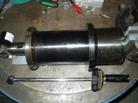
Nut_Driver.jpgSpindle_housing.jpgSpindle_in_press.jpgSpindle+parts.jpg
 
I did not need the spanner to take off the two remaining bearing nuts. The top nut was Loctited and came off with some heat. The bottom nut turned right off. The reason for the bearing failure appears to be that someone left the O-ring out that seals the spindle to the face plate. The face plate to spindle housing O-ring was there.
The two angular contact bearings are 2MM9112WI Fafnir. Someone etched out the 2 and wrote 3. Fafnir makes 3MM9112WI bearings which are the next grade up (Abec 9). Perhaps they were being optimistic?
 
Whilst waiting for the spindle bearings I wanted to find out I could tighten the play in the Y axis. When tightening the vice on the table the dial indicator shows 0.004" of movement. I took off the servo and coupling. When I loosened the bearing collar it was not tight against the bearing. On this early version you were supposed to use a pnuematic piston to preload the bearings and then hand turn the nut until it just touches. I do not have one so I used the dial indicator to check the play. I got it down to 0.001" pushing both ways. Any tighter and the bearings started rumbling so I thought the bearings were bad. You are supposed to be able to push out the bearing housing by pushing the table back after removing the nut and bearing pack mounting bolts. That did not work so I tried a soft drift against the end. The drift was also hitting the outer race of the bearing. It moved about 1/2" then was stuck. I finally got the housing out when I used the drift just on the housing. These housings have a centre web with needle bearings on both sides and then ball bearings. Turns out the needle bearing nearest the ballscrew shoulder had desintigrated and was cutting into the shaft. The only way that I could get in there was to unbolt the servo mount and slide it back over the ballscrew. After knocking the spacer and ball bearing back against the shoulder of the ballscrew I was able to get in there with a jewlers file and remove the burr around the groove. I am going to replace the ball/needle bearing pack with a angular contact bearings.
Ballscrew_needle.jpgBallscrew_groove.jpg
 
I'm all for doing things yourself but with the Haas spindle replacement only $5000 why did you take it on your self to try to rebuild it? If you are like the rest of us working 10 hours a day to get 80% spindle utilization you have lost 40 hours of production since your first post. Now assuming your shop rate is $75.00 per hour then you have lost $3200 in revenue on a rebuild that may or may not be right. If you use the correct bearings then that about $1600 so now you are at $4800 and still have not completed the rebuild.

I am not knocking what or why your doing it yourself but the whole purpose of the Haas spindle cartridge is fast replacement. It is a given it will go out every 5 years like clockwork. When I blow a spindle I call before 5PM and a new one is installed before 12PM the next day (with a warranty). I see how it could be interesting to play around with a rebuild but a bit to risky for me.
 
If I had a backlog of outside work that would be the case but I am still setting up to do prototype work so spending $5000 with nothing to write it off against does not sound economical. Also, this is a '91 machine and Haas does not have all the parts for it. Mostly I prototype my own designs then send them out to another shop to produce them to add to my sales list so I can spend the time designing other parts.
The spindle bearings (OEM) were $305. Some outlets had the same bearings for over $1000. It pays to look around.
 
Understood about the no backlog. As for the OEM bearings you need to be careful. You will find the numbers may match but but the class is off. When I used to do the spindle rebuilds on manual Knee mills in the 90's I would pay $900 for Torington gold series. I tried plain off the shelf bearings once but they shot after about two-three months.
 
I'm very interested in both the spindle rebuild and especially the thrust bearing. I was shocked to find a $10 pair of bearings with no means of lubricating without disassembly. I took a quick glance at what bearings were available and thought it possible but no time to fool with it.
I look forward to seeing how you did this.
 
The lubrication on the needle bearings did not seem to be the problem as there was still grease in there. One problem with these needle bearing designs is that there is nothing but the shaft to keep the needle cage centered so the cage wears on the shaft. Since the needles are cylindrical they have to skid somewhere along its length which eventually causes fretting of the needle and/or washer.
A friend had a spare later model thrust housing that uses two matched angular contact bearings. I put that in and then had to back off the backlash parameter quite a bit.
Putting the bearings back on the spindle was easy. I put the spindle in the freezer overnight and the bearings dropped over with hand pressure. The nose plate went on first with a -158 Buna O-ring on the top surface and a -041 Viton quadring in the spindle nose groove. The Timkin catalog gives 360N (80lbs) preload for the DUL bearing. It turns out this is not as much load as you would think. The bearing nut is 2.360" x 18 TPI (2.26377" PD) so one revolution moves the nut 1/18" which gives a thread angle of 0.44757°. Without friction, the force on the nut along the shaft is 128 times the force perpendicular. So 0.625lbs perpendicular gives the 80lbs preload. I tightened the nut as tight as I could by hand to seat the bearings then backed off and retightened The lock nut went on with red loctite in the upper threads.
The spindle and bearings went in the housing with light pressure from the press. Then the top 6010 ball bearing went on. The bearing nut was put on with the wrench that I made and torqued by standing on the end of an 18" long 3/4" drive handle.
I finally got the spindle back in after several tries. The first problem was that I should have used round O-rings on the aluminum spacer above the Belleville washer stack instead of the quadrings. The -215 quadrings were hanging up in the snap ring groove and made the spacer difficult to install. I put in the snap ring that was missing above the aluminum sleeve. I had to push the sleeve down in the press to get the snap ring in place. I trial fitted a tool holder using the press to move the drawbar. After I got the spindle back in the head the tool would not pull up into the taper. I took the spindle and the drawbar back out and tightened the nuts over the Belleville stack to allow the drawbar to move further up before hitting the sleeve. This might have been the reason for the snap ring being missing. After putting the spindle back in the drawbar would not move far enough down to allow the retension knob to go past the drawbar balls. The piston was moving almost 0.2" before it contacted the end of the drawbar (My air piston is a rounded corner rectangle without a snap ring, not the round piston with snap ring. The piston is stopped by the mounting surface). I do not know if something is missing in the drawbar stack but I made a spacer to sit on top of the drawbar to take up the space. Now it appears to be working correctly.
I found the instructions for installing the spindle unworkable. It is very hit or miss to align the spindle with the head by dropping the Z axis over the spindle and not sticking the spindle in the bore because of misalignment. I put the spindle on two 4x4 wood blocks and dropped the head down over the bearing nut threads of the spindle to just above the body. Then I put a scissor jack between the blocks and lifting the spindle as I moved the spindle around to align it with the bore.
After sweeping the spindle with a jewlers indicator I put the two shims back in between the spindle flange and head. The belt tension is impossible to set precisely without special tools. 9/64" deflection with 3-6 lbs force (prior to 10/91). No room to get in there except with a prybar and visually measuring the deflection.
Somewhere I read the spindle should be run at low speed for half and hour to distribute the grease and run in the bearings. The spindle now makes less noise than the rotary converter that powers it. Next is to finish all the alignments and make side loaded cuts to see if all the chatter problem is fixed.
 
Thanks for the details on the spindle. Being on a tight budget it may be an option on the old girl one day.

Yea getting the spindle back in is a bit of a trick. I used the vice unbolted to table and on a plastic bag [two layers]. Clamped the drive keys just tight so it would not fall over. S l o w ly lowered the head down while making lateral adjustments, once engaged I got within 1/8" to flange installed bolts and loosened vice.
Shimming square was a tedious task but she is square and true.

Did you install the big retaining nut, I left my just pushed with screwdriver tight.
 
I used an aluminum rod to tap the nut around tight then set the two set screws to keep it from loosening. I reset the home positions and parameter 64. Now it makes almost no noise when changing tools. I found a trick to getting the belt back in from the top. Twist it as though you were coiling a band saw blade so the teeth face the gear change. Then you can slip it under and untwist to get it around the gearbox pulley.
 
Backwards! I made the ASSumption that whoever was in there before knew what they were doing. The missing O-ring in the nose plate that wiped out the bearings should have been a clue. After running in the spindle at 500 RPM for two hours then 1000 RPM for 20 minutes the temperature inside the spindle was over 180°F. Looking at the assembly, my original thought that the preload was from the bearing nuts was wrong. There is an inner and outer spacer between the bearings so the preload is determined by the relative thickness of the spacers, not the nut torque. Timkin's Super Precision Bearings for Machine Tool Application Catalog (Fafnir was bought out by Timkin) shows the bearings face to face or back to back. For a vertical mill they show the mounting should be back to back (thick side of outer flange together). Mine was face to face. I reversed the bearings and now the spindle is running much cooler. The bearings nuts should be torqued tight.
The catalog also shows the higher precision 3MM-WI bearings are a 25° contact angle and the 2MM-WI are 15° contact angle so whoever etched out the 2 and wrote a 3 was blowing hot air. The 2MM-WI operate at a lower temperature for a wide range of speeds and are recommended for rigidity in both axial and radial directions. 3MM-WI are recommended for predominately axial loading such as a lathe. The bearings also have a mark showing the outer race high point which should be aligned with each other when assembled. I wish that I had found this catalog before buying the bearings but they are in there now so I will go with it.
I had originally increased the high gear orientation speed due to the increased drag of the flange seal and bearing friction. 4 was too slow and the spindle would stop from the orientation pin friction and 5 was too fast and not lock. Now it is back to 4 and locks.


Back
Top