What's new
What's new

1981 - Shizuoka B3-V Slideway Condition

pbrubaker

Aluminum
Joined
Sep 14, 2015
Location
Gaston, Oregon
Hey all,

I'm back with more of my Shizuoka VMC. I finally got the machine cleaned up, and took some measurements and photographs of the ways. Let me preface that this is my first rebuild (and definitely not the last,) I have spent a fair amount of time researching the subject, but I'm still a noob.

I could use some help assessing the condition of the slideways, and whether or not they need to be repaired. And also, if it doesn't require repair should I just go through with a grind/slideway material because I have it all apart, and there will be added benefits to using a bearing material.

Lets get to the meat. Here is a gallery of the shots I took during disassembly and cleaning. Coolant infiltration was a big problem that I intend to fix. There are many ways to improve the drainage and keep it off the machine.

Way Condition Gallery

Second, here are some detailed shots of each slideway and the corresponding measurements I took. Also I will list the things that are bothering me with each way and specific questions with regards to them.

IMG_0333(1).jpg

Bed WaysLeft WayRight Way
E2->E1E1E2E3->E2E2->E3E3E4E3->E4Surface Variation
0.0001-0.0001-0.0003-0.0001-0.0001-0.0001-0.0002-0.0006-0.0002-0.0001Max0.00010
0.00020-0.0004-0.00030.00010.0001-0.0003-0.0007-0.0003-0.0002Min-0.0005-0.0007
0.0001-0.0001-0.0004-0.00030.00010.0001-0.0004-0.0006-0.0003-0.0003Average-0.000188889-0.0003
0.0001-0.0001-0.0005-0.000300-0.0004-0.0006-0.0003-0.0003
0.0001-0.0001-0.0004-0.000300-0.0003-0.0005-0.0002-0.0003Parallelism
00-0.0003-0.0002-0.0002-0.0001-0.0003-0.0004-0.0002-0.0002Max0.0002
0-0.0002-0.0002-0.0002-0.0001-0.0002-0.0004-0.00020-0.0001Min-0.0003
0-0.0002-0.00030.000100-0.0002-0.0003-0.00010Average-0.00004
000.00010000-0.000100(Datum)

Note: The En->En are parallelism measurements from edge to edge. A granite straight edge was clamped to one edge and a surface gauge was run along it's edge. The other 6 columns are surface variation from the front edge of the ways. Imagine you're looking top down on the ways.
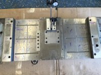
  • The numbers here look great to me.
  • Coolant got into the oil grooves, and corroded the top surface as it sat.
  • The surface is pitted, I know this is not good, but just how bad is this?


IMG_0353(1).jpg

Saddle Ways (bottom)Left WayRight Way
Surface variation+/-.001+/-.002

Surface Measurements(with .010" gauge block)
Position (left to right)123123
-0.0015-0.0005-0.0015-0.001-0.0005-0.001
-0.0015-0.001-0.001500-0.0005
-0.001-0.00100.00050-0.0005
-0.001-0.00150000
-0.0005-0.000500.00050.00050.001
-0.001-0.00150000

Parallelism
Position (top to bottom)E2->E1E2->E3
0.0010.002
00
0.0005-0.0005


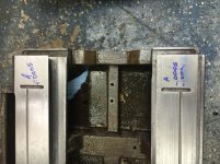
  • I'm the most concerned with the saddle.
  • The bottom surface doesn't look terrible but the relief in the middle of the saddle should probably be deeper.

IMG_0337(1).jpg

Saddle Ways (top)Surface VariationDovetail Parallelism (per 6")
MaxMin
Dovetail 1-0.00050.0005??Haven't made a King-Way yet…
Dovetail 2-0.002-0.0005


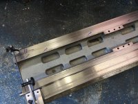
  • These are definitely the worst of the bunch IMO.
  • Coolant got into the oil grooves again, and swarf got under the table and grooved the way.
  • I'm not a fan of oil grooves and scraping on the bottom surface, I'd rather have both on the top surface so things can be flushed out, rather than stay in. Wipers are more effective too. I think the condition of these ways makes the argument in favor of that practice.
  • The surface is grooved pretty badly.
  • Variances of about 0.002" (again measured with the granite straight edge as a parallel.)

IMG_0349.jpg

Surface VariationDovetail Parallelism (per 6")
Table WaysMaxMin123456 (Datum Point)
Dovetail 1 (top)-0.0003-0.0001-0.0005-0.0005-0.0008-0.00070.00050
Dovetail 2 (bottom)-0.0006-0.0003


  • Given what the other side of this slideway looks like, I'm surprised the table's ways look so good. (I didn't check hardness.)
  • These numbers are also better than I was expecting.
  • I'd like to move the oil ports and grooves to this side of the way. And I'd like to consider bearing material for increased speed of this axis.

I know the numbers don't look too bad, but there are some things I think I should deal with, but I welcome any and all opinions. I'm the type of person who usually bites the bullet and does things right the first time. And I've already put a lot of time and effort into this machine, so I'd really like to see it go back together as good as it possibly can.

That being said, I've only watched scraping videos, and I've never held a scraper. And I've read/watched as much as I could on slideway bearing material application, but there are some gaps there. How are the surfaces prepared? How much do I tell a grinder to take off? I'm a fast learner, and skilled with my hands, should I attempt learn scraping to scrape in the bearing material, or hire a pro? I know I'm getting a little ahead of myself here, but I just wanted to give you guys some of the questions I have.

I'm currently reading "Machine Tool Reconditioning" and "Testing Machine Tools" but both are slow going for me as they are a little dry for my tastes.

Anyway, I appreciate any guidance you care to provide, and I will update this thread as I progress along in this first rebuild.

Cheers,

Pete

Here's a link to the full photolog gallery and what I've been up to on this machine.

Shizuoka Millmaster B3-V Rebuild Gallery
 
Also, I forgot to mention the column ways. They are perfect. The bearing material looks as though it needs to be replaced. I haven't measured the thickness yet, but it's difficult to catch with my fingernail if I scratch across an edge. The gibs are also coated, and some sides the bearing material is barely visible. I'll take some photos of those tomorrow.

Again, any help/comments are appreciated. Thanks for reading.
 
I will be honest that my eyes glaze over when I see figures like you have posted. To me they are only useful when actually doing the rebuilding to see how far I have to go rather then using them to determine what sort of tolerances the machine will hold.

For me generally I will think about rebuilding when the machine cannot hold the tolerances I expect of it.

Generally it means doing all the practical measurement tests before pulling it apart.

Are the ways on that mill hardened? I would nearly expect them to be.
 
Those figures look pretty good to me for a machine that's seen some action. I'd only get worried if I couldn't produce accurate work on the machine.

If the anti friction material is showing signs of serious wear that's another story. It sounds like that will have to be replaced. Some scraping will certainly be involved then.

The actual physical process involved in scraping is not hard to learn but it's
knowing where to scrape and how much to take off were the skill is. Plus knowing how how to set the job up for optimum results.

You will also need a certain amount of tooling and equipment that isn't all that easy to come by these days.

Regards Tyrone
 
Set the table on 3 - 1 2 3 blocks ground to the exact size at 30% from the ends. 2 on one end 30% in from the side edge or under the ways if possible and then 1 in the center of the other end. This is a better method then laying it directly on the plate and on cardboard. Most of the time scores are caused by lack of oil and not swarf. The straight oil grooves cause problems too. The opposite side that rides over the groove will not wear and you get unworn ridges as wide as the groove. If your just going to clean it and assemble it, Before assembling it either use a scraper to "square cut" or checkerboard both sides of the ways and 1/2 moon oil-flake the top side. Be sure to use a round lapping stone and stone the oil groove edge too. It's nice to see you being a detective measuring your wear.

Next time you take measurements find the lowest spot and make that zero and measure plus as that is where you will be scraping if your were to scrape it. Less chance of making an error. I also don't write .001" I write 10 or 10- tenths. or not .0013" I write 13. less writing and easier to visualize the surfaces.

Setting the saddle and table on a plate and not on 3 points is a learning curve you will understand after you re-check it on 3 points and see the difference.

Go to a professional precision shop and where an old timer inspector and machinist works and watch him use 3 points all the time. Many call scraping is a lost art...I say using 3 points is a lost art too. Rich
 
I will be honest that my eyes glaze over when I see figures like you have posted. To me they are only useful when actually doing the rebuilding to see how far I have to go rather then using them to determine what sort of tolerances the machine will hold.

For me generally I will think about rebuilding when the machine cannot hold the tolerances I expect of it.

Generally it means doing all the practical measurement tests before pulling it apart.

Are the ways on that mill hardened? I would nearly expect them to be.

I understand your point, but the machine was non-functional when I acquired it. So I couldn't do any measurements of it's performance prior to disassembly.

I got it to clean up and do a control retrofit on, and upon disassembly I found some things I didn't like which lead to more disassembly, and eventually where I am now. I don't think the ways are hardened. I can scratch them with a file.

Set the table on 3 - 1 2 3 blocks ground to the exact size at 30% from the ends. 2 on one end 30% in from the side edge or under the ways if possible and then 1 in the center of the other end. This is a better method then laying it directly on the plate and on cardboard. Most of the time scores are caused by lack of oil and not swarf. The straight oil grooves cause problems too. The opposite side that rides over the groove will not wear and you get unworn ridges as wide as the groove. If your just going to clean it and assemble it, Before assembling it either use a scraper to "square cut" or checkerboard both sides of the ways and 1/2 moon oil-flake the top side. Be sure to use a round lapping stone and stone the oil groove edge too. It's nice to see you being a detective measuring your wear.

Next time you take measurements find the lowest spot and make that zero and measure plus as that is where you will be scraping if your were to scrape it. Less chance of making an error. I also don't write .001" I write 10 or 10- tenths. or not .0013" I write 13. less writing and easier to visualize the surfaces.

Setting the saddle and table on a plate and not on 3 points is a learning curve you will understand after you re-check it on 3 points and see the difference.

Go to a professional precision shop and where an old timer inspector and machinist works and watch him use 3 points all the time. Many call scraping is a lost art...I say using 3 points is a lost art too. Rich

Hey Rich,

Thanks for the tips here. I actually did use the 3 point method for all but the bottom of the saddle ways. I spent a lot of time searching and reading about rebuilding/measuring and scraping here, and read many posts from you, Tyrone, RC99, and Forrest. It's nice to have all this information in one spot, even if it's sometimes difficult to dig through.

I used 2 123 blocks with a machinist jack in between, and leveled them with my spirit level in both directions prior to taking measurements. By the time I got to the saddle ways I had pretty much decided that I wanted to get some work done on these so I didn't bother with taking super accurate measurements of it.

Good idea to save writing by just counting positive tenths. I'll do that next time.

Now, I've been giving this a lot of thought since writing the initial post and I think I've decided what I'd like to do. I don't care if this machine is fast, but I do care if it's accurate. I also mentioned I like to do things right. I have it all apart now (for hopefully the last time in my life.) There are some problems I would just prefer to deal with now, instead of worrying about when I will need to deal with it in the future. I want to move the oil grooves for the table from the bottom of the sliding surface to the top, I want to clean up the saddle ways, and I want to add something to reduce the friction between the two surfaces and prevent metal on metal wear. Also, I'm going to be replacing the Turcite/Rulon on the column slide anyway.

That being said, I'm making a trip to LA today or tomorrow to drop the parts off at my grinder. I have to drive up there anyway to drop the ball screws off for inspection/repair, and the grinder I use is very reasonable. Once back from the grinder I'll apply Rulon, fly cut it, add oil grooves, and scrape it in. (out of all the things I searched for on the forum, this was the topic/process that I found very little detailed information on. IE: what are the various methods that can be employed to true up the new rulon?)

I have done a lot of research on the subject of rebuilding, but a few things aren't clear.

1) How should I specify how much to remove? I know the thickness of the Rulon, the depth of any imperfections, and dovetail angle all play a part in how much is removed from each surface. This isn't their first rodeo on this stuff either, and I really like working with them so I'm not too worried about getting it right, but it would be nice to know more about this process before showing up at their shop.

2) What tolerances are reasonable for flatness/parallelism?

I guess those are the two major questions I have right now. Some more information about the process of machining/scraping the rulon after bonding would be helpful but I'm not there yet.

Cheers,

Pete
 
Just to be clear, your going to do you pre-machining by having it ground? Is that for the Rulon side or the mating slide?

Regards Phil.

I was going to have all the ways on the saddle ground. The dovetail ways are stationary, and the box ways are sliding. So one mating surface, and one sliding surface. I think the table is probably fine, but I was going to take it to them so they could check it out.

Do I have something wrong here?
 
I looked at all the pictures again and it is a combo saddle box way and dovetail way table. The table rides on the saddle much like a Bridgeport table rides on the saddle and the saddle rides on box base ways. But the table seems to run past the saddle and exposes the saddle ways.


The design is bad especially with the straight oil grooves no mater what side they are on. You say your going to mill out the oil grooves in the saddle, How deep are they? 99% of the machines that use Rulon / turcite the is on the unexposed side, but from the pictures it looks like the table moves to the left and right exposing the saddle so putting on the top of the saddle would open it to chips and wear. You could put Rulon on there and and cover up the deep oil grooves and then you would have to make some new way covers. I did a Hitachi Seiki VMC and it was turcited on the exposed side and worn, The owner told me to put the Rulon on the same side because it had run production for 15 years that way even with an obvious engineering flaw. I used an extra hard Rulon I bought from Tri-Star.
__________________________
You wrote

Now, I've been giving this a lot of thought since writing the initial post and I think I've decided what I'd like to do. I don't care if this machine is fast, but I do care if it's accurate. I also mentioned I like to do things right. I have it all apart now (for hopefully the last time in my life.) There are some problems I would just prefer to deal with now, instead of worrying about when I will need to deal with it in the future. I want to move the oil grooves for the table from the bottom of the sliding surface to the top, I want to clean up the saddle ways, and I want to add something to reduce the friction between the two surfaces and prevent metal on metal wear. Also, I'm going to be replacing the Turcite/Rulon on the column slide anyway.

That being said, I'm making a trip to LA today or tomorrow to drop the parts off at my grinder. I have to drive up there anyway to drop the ball screws off for inspection/repair, and the grinder I use is very reasonable. Once back from the grinder I'll apply Rulon, fly cut it, add oil grooves, and scrape it in. (out of all the things I searched for on the forum, this was the topic/process that I found very little detailed information on. IE: what are the various methods that can be employed to true up the new rulon?)

I have done a lot of research on the subject of rebuilding, but a few things aren't clear.

1) How should I specify how much to remove? I know the thickness of the Rulon, the depth of any imperfections, and dovetail angle all play a part in how much is removed from each surface. This isn't their first rodeo on this stuff either, and I really like working with them so I'm not too worried about getting it right, but it would be nice to know more about this process before showing up at their shop.

2) What tolerances are reasonable for flatness/parallelism?

I guess those are the two major questions I have right now. Some more information about the process of machining/scraping the rulon after bonding would be helpful but I'm not there yet.

Cheers,

Pete[/QUOTE]

_______________________

Why not let the pro's do it if they know what they are doing? If you hired me to do it I would probably leave the base box ways alone. If you wanted to do the bottom of the saddle I would either just touch up the saddle bottom ways and 1/2 moon them and run the way they were designed and originally made may need to relocate the ball nut a little.

If you have anything ground, tell them to grind off the same amount on each side. If one side cleans up in .005, and the other side in .010, then have the take .005 off the other side.

Most Asian machines use .047" thick Rulon and they scrape it. I don't know any rebuilders who fly cut it after installing it. I may have milled it once. New builders may grind it but they have all found out you have to scrape it with .002" deep oil pockets or they get stick slip. When you cut the oil grooves zig zag them and not straight lines. It ooks like your headstock ways have a machined slot the that the rulon rests in. it's late and I can't type anymore. Rich
 
Rich,

Thank you so much for your replies. I took your advise and had them grind the top of dovetail ways on the saddle parallel with the box ways, and if necessary to grind the inside of the dovetail, but they said they would check it first.

When I was considering Rulon for this axis, I was going to install it on the table ways facing down. I wanted to fill the oil grooves for this slideway, and add them to the table ways facing down. It was in my plan to add some better protection for these ways, and the ball screws. I had planned to add way extensions to the saddle, wipers, and fab some telescopic covers.

When touching up the box ways on the saddle, should I modify the oil grooves (add any zig sags?)

You are indeed correct that the Rulon appears to be pressed into the oil grooves on the headstock. If I replace the Rulon here should I fill that and cut the zig-zag grooves into the Rulon directly?

I had talked to a couple of rebuilders that fly-cut then scrape the Rulon so I assumed that was SOP.

I will need to get some equipment, but I hear that you can help with that? Considering how much help you give folks like me, I'd like to purchase what I need through you.

Cheers,

Pete
 
Yeah, that's why all the trouble. It's built like a brick shithouse, that's the main reason I sought these out. Sorry that wasn't clear.

I'm retrofitting the control to LinuxCNC and my main goal with this machine is accuracy/repeatability. I know I can map and correct error in the control, but I want to get things as close as I can before turning to that.

Also, I really don't want to take it apart again. I was taught to do it right the first time.
 
If you are going to fill the oil grooves with a epoxy like plastic steel, be sure to use a die grinder to grind the bottom or the groove wider to help hold it in. Another thing is to use a propane hand torch and heat up the cast iron to sweat out the oil filled iron. I do that to ways that I turcite too. When I fill the grooves that will be seen i usually use plastic aluminum as when it drys its shinny like cast iron. If your going to go to the extent you seem to be going too,you might will and drill out the grooves and make cast iron inserts and make a .0005" press. also drill air holes under them so when you press them in the air doesn't compress and not let it seat in the hole.

When you make wipers put a wedge behind them so the wiper pushes the crud off the ways. Like a snow plow or road grader moved snow and dirt to the side.

Another tip is I figure the glue under the turcite on the head is old and might be ready to release, so I usually replace the Z turcite too while I am at it. Thereis a pretty simple method to test the glue. Take a plastic handled screwdriver and tap the turcite and where the glue is loose you will hear a hollow slap sound compared to a solid noise where it is tight. Also check the gib and if they are loose, time to change. Besude to Zig zag the gooves or diamond shape them and never cut in straight grooves as you saw why.

If you want to buy a new power scraper give me a call..I don't sell the ink or hand tools...to much hassle for a few dollars profit. You call Ed Dyjak 248-684-4260 as he sells small order everything. I can get you a discount from Dapra too. Just call Matt 1-800 243 3344 and tell him your a student of mine and he will give a small discount on some sales. The NC class were going to pool their order into one to get a discount from Matt. I do as do others on here sell CI straight-edges too. Rich
 
I was going to have all the ways on the saddle ground. The dovetail ways are stationary, and the box ways are sliding. So one mating surface, and one sliding surface. I think the table is probably fine, but I was going to take it to them so they could check it out.

Do I have something wrong here?
I'll admit, I haven't spent enough time studying your problem. Might be an Australian thing. Your initial figures just did my head in, R.C had problems with them also.

I was just checking if you were intending to lay down new Rulon, on a freshly ground surface, Or were regrinding the ways and Ruloning the saddle. I guess I've missed the part about you pre-machining for the 1.2 or 1.6mm of slippery goodness.

I'd never lay Rulon / Turcite upon a ground surface. That's all I was checking on.

On the other hand, its almost obscene how I can rough mill, burn, boil, flame, solvent clean for Turcite glue.
 
172379d1464305155-1981-shizuoka-b3-v-slideway-condition-img_0353-1-.jpg


It's been doing my head in for a week, since you posted this.

The extreme left & right of your photo They are retainer / keeper plate faces. They have never seen a minutes worth of wear. It's a Static face. They are ground back at the Shizuoka factory. This is the playing detective part of the equation.

You have units assigned to them. I can see a plus 0.002, +0.001, +0.0005, -0,0005 (best that I can read them from that pic).

You have a 0,0025" two and a half thou spread. Those lands, being ground are gospel. If you were on 3 points like Rich or I would do it. I'd bet those retainer lands would look better than a thou. If you piss about with a tenth clock, your sure to find at twist. That could have been there the day it was born,

Top side of your picture was +.002 and +001. Drop them down so you have a datum, then you can tell wear.

Regards Phil.
 
Sorry to be a Turd, but this has been doing my head in for the last week. I understand your trying to do the best job possible. This is not a valid test.

You have a massive overhang of the arm there .Any Yaw or Roll of the way the base is sitting on, will give you wild results

172380d1464305161-1981-shizuoka-b3-v-slideway-condition-img_0349.jpg


You need a 3 point system that spans both ways. Or a straight edge that qualifies one edge and a big micrometer that checks one dovetail to the other over roll pins.

But that arm thing, that's like an octopus reaching out 8 -10 times it's body.

You're not being a turd. It was the only way I could even attempt this measurement at the time. It repeated well enough for me to get an idea of what was going on. I was using 5/8" dowel pins in the dovetails. I selected three out of a box that were within a tenth of each other in diameter.

I have since purchased a micrometer large enough for this measurement. When it arrives I'll repeat it.


Back
Top