Richard King
Diamond
- Joined
- Jul 12, 2005
- Location
- Cottage Grove, MN 55016
I lecture this when I speak at SME Events, teach in my class on how many people will lay a mill table, grinder table and scrape them with a straight-edge and King-Way type gage and when the machine is finished it cuts off or when they are scraping the mating surface they can't understand why that surface is not coming in. When you store parts, test parts and scrape parts you need to put them on 3 points to eliminate twists. Everyone knows you can bend a lathe bed when it is cutting twists and can be aligned by adjusting leveling screws. So you know cast iron bends and if you take apart a machine and store a table on wood, on a skid, leaned against a wall it will bend over time.
If you set the parts on horses, a wood or steel table you are assuming they are perfectly the same height, the concrete floor floor is level, etc. To eliminate all those issues you set the parts on 3 - points. If you have a bent table and lay it on a granite table thinking it will be OK, scrape it and then lift it off the flat granite the table will be bent. To eliminate the issue, you put it on 3 points and it fine.
Below is one of the things I show in my classes. We take a Bridgeport table and set it on saw horse, then I have students check the twist with a King-Way, record the measurements. Then have them put the table on 3 wood blocks and re-check it. It is always better and by a lot. So if a new scraper starts to scrape the table when it is already twisted it will be screwed up when it is done.
This was tested at the recent Bourn and Koch plant in Rockford IL where we had a rebuilding class.
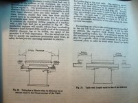
Check worn Bridgeport on 3 points, check Monarch EE saddle on 3 points. Small shim under bar on left. Using a 60year old HK-100 mini King-Way to check dovetail parallelism.


.jpg")

.jpg")
If you set the parts on horses, a wood or steel table you are assuming they are perfectly the same height, the concrete floor floor is level, etc. To eliminate all those issues you set the parts on 3 - points. If you have a bent table and lay it on a granite table thinking it will be OK, scrape it and then lift it off the flat granite the table will be bent. To eliminate the issue, you put it on 3 points and it fine.
Below is one of the things I show in my classes. We take a Bridgeport table and set it on saw horse, then I have students check the twist with a King-Way, record the measurements. Then have them put the table on 3 wood blocks and re-check it. It is always better and by a lot. So if a new scraper starts to scrape the table when it is already twisted it will be screwed up when it is done.
This was tested at the recent Bourn and Koch plant in Rockford IL where we had a rebuilding class.
Check worn Bridgeport on 3 points, check Monarch EE saddle on 3 points. Small shim under bar on left. Using a 60year old HK-100 mini King-Way to check dovetail parallelism.
Last edited:


") They look horrible! And I need to finish them.
They look horrible! And I need to finish them.  Haha!
Haha!