What's new
What's new

Airy Points

ironsmith89

Aluminum
Joined
Aug 29, 2014
Location
lennox, sd, USA
I wanted to pick the brains of some of the experts out there regarding the equation for airy point spacing. I have always used Length X .577, however in reading Moore's Foundations of Mech. Acc. I noticed they address two different constants for obtaining their spacing. On pages 27 & 28 the constant .544L is used on their straddle gauge, while they don't call them airy points here, it's basically what their description eludes to. Turning to page 123 they describe "Airy Points" and the .577L equation I'm familiar with.
To throw another monkey wrench in the system, most of the machines I rebuild at work have their tables sent out for grinding. When they come back I give them thorough inspection on airy points with levels, mic for taper etc. etc. In doing this inspection I can usually see the marks left on the flat ways under the table where they rest it to grind the top, and I have seen two shops who use .500 X length as their spacing. Most of these tables are over 8' long, which really changes the spacing depending on which equation you use. For example one common length is 107"
107 x .577=61.739
107 x .544=58.208
107 x .500=53.500
Am I splitting hairs here? I feel this Is too much variation to ignore. I myself as I mentioned use .577, however two different rebuilding shops I can confirm use .500. When I inspect their work resting at .577 I do get an error in overall straightness of approximately. 001-.002 usually with the ends high which makes sense.
I just wanted to gather a few expert opinions on the matter.
Thanks
Chris German
 
I would blindly trust what Moore published.
They put a lot of effort into what they published. If it was wrong, a peer review would of certainly caught the error.
.5 vs .577 seems like a shop floor change for ease of calculation.
I have heard a couple of different numbers myself.

That's interesting that the ends move that much when you change the formula.
 
Well to be honest I can't say I've checked their work at the .500 spacing they were ground on. I never thought twice about the error as these are as mentioned over 8 feet long and it's for a milling machine so within spec for what I'm after. When I have to scrape and straighten tables myself it's inspected at .577 spacing on 3 points. Next time we get one ground I'll check the various positions and see if it actually changes.
Chris German
 
Here we go again. Science, theory and experience.

I never used Airy points until I met DR. Archie C, I always called them the swivel points or Rotation of points.

I can offer advice I was given years ago from my Dad; Richard Visinor a PHD in Egineering who worked at Honeywell; Co-Owners of Air Bearings who do a lot of super precision grinding and worked with Moore; Tru-Stone / Starrett.

DR. Visinor worked at Honeyweel in their "think Tank" and He told me .707 x L divided by 2 on a square no matter how long it is. The co owners of Air bearings inc. Told me the .707 figure was correct but for a rectangle that most machine parts are is to close to the center and told me that if I used 30% from the ends was good enough. They said the math for the perfect calculation for lab works was close to 29%. Tru-Stone uses 25% (something) on the surface plates. I have thought about this a lot and if I am setting up a part, I look at the design and where the heavy part of the casting is.

In Taiwan we set up a VMC column casting and it is a trapezium. Had to Google shapes to find what it's called. If I used 1/3 or 30% or 25 % or .707 you get different spots. What I did and showed them, is I use the old fashion way. Played Detective. I layed a pipe on the floor and set the column on it to find the balance point then I calculate where to place the 3 points. I used 20% of the center (both ends) of that center balance point or 30% + 30% + 40% = 100%.

I showed this to the PHD machine designers and got approval. On rectangular parts like a Mill table I use 30% from each end and 30% from each side to locate the 2 points and the center of the other end. to locate the single point. I also use small jack screws around the perimeter finger tight when a mill table in on a machine to be machined, Block around it to hold it down.

As Archie C our professor on PM taught me a mill table bends due to peening. When I set Mill tables up to measure, to mill, to grind, to plane I use 4 same size ground bars approx. 2" x 4" x 6" placed at 30% from the ends on the ways plus use jack screws around the perimeter again.

So for machine tool rebuilding purposes you can't use the typical calculations to find the location points. You need to figure out where the weight is to locate the points. Take a look at machines; A sip double column jig bore locates the 2 point side under the column uprights on the one end and the single point is centered under the table travel. I have seem machines like a Blanchard grinder sitting on 3 points, but they are placed at the out side ends. So there is no one good answer I would say. Rich
 
Thanks for your information guys, I have wondered if the 30% rotation rule played a part in this. I believe these large machine tables I'm working with are long and thin enough that they will conform under any position of the support, I just wanted to answer a question I've had for a few years now as to how picky it is.
Chris German
 
http://www.google.com/url?sa=t&rct=...eoIgDjvgoEmpjg0FA&sig2=V0IOKkqNs250GmZ1Pb_LkA

The link is to a brochure from Awea which refers to the use of Bessel points as providing the least deflection of the table. From the pictures they are not just talking about using them. The first mention is on page 6. Page 14 has the best pictures of the ways, and page 15 shows scraping of the ways. Rich- are you familiar with this company?

Until reviewing the Mitutoyo information I had not realized that the Airy points are calculated to provide parallel ends. The Bessel points provide the least deflection of the surface- which is what we are concerned with. This makes me wonder why we see so many references to supporting surface plates at the Airy points. In reading about Bessel points I did find two German surface plate manufacturer who uses Bessel points.

As Richard implies- on machines we are not dealing with the solid uniform structures like surface plates where the calculations are easy.
 
you might be surprised at how little force is required to deflect what appears to be big rigid castings
.
i have had cnc mill jobs where program M0 says jack up one corner with a screw jack .0010" and it takes little effort, can easily bend casting .005"
.
i think of it like picking up a 1" round steel rod 20 foot long. even if you pick up at airy points which minimizes sag it does not eliminate sag 100%, you can still have a wavy surface to some extent.
 
Tom Your an active machinist on high precision machine tool parts and casings. When your setting up a long part or casting where do you set the blocks? Do you start with 3 points and block to it for stability and then set jacks around the perimeter? Where do you place them? Have a rule of thumb you use?
Thanks, Rich
.
fixture i use are normally designed by others and sometimes support locations are not at optimum spots but spots where a already machined part of casting sits on a support pad. many large castings are not machined all across whole length but only in certain small spots.
.
i have seen where on the milling machine in fixture a casting measures flat within less than .0005" and inspections says a particular corner is always .001" off. so machinist has 2 choices either adjust corner so it reads .001" off on the machine and fixture but inspections measure it flat OR move a support pad closer to airy point. i have seen where a support pad was moved about 1 foot and the flatness readings on machines agreed with inspections readings. inspection puts part on a big surface plate and uses 36x36" granite square and .00005"indicators.
.
i have also used a special electronic level to take readings every 4" and it graphs flatness out to show error amplified on a computer printout
.
usually finish milling cuts of less than .001" i have to watch the cnc mills servo diagnostic screen. there are times i have to wait 10 seconds or longer for servos to stop moving up and down .0005". you can only see the machine moving back and for on servo screen or have a .0001" indicator attached to spindle reading the part. thats why wavy surface is a common error.
.
another common error is when a top surface is milled the part distorts and when casting is flipped the bottom now positioned at the top is no longer flat because of part distortion when material is removed. it can be tough to get perfect flatness and parallelism and perpendicularity to within .0005"
.
cutting force can push part away from cutter and when cutter moves farther away on the part a section machined goes back up. also a milling cutter over harder metal does not want to bite in or penetrate as far and i have seen once off a hard spot it goes straight down leaving a ring, arc or circle as cutter went straight down penetrating metal .0003" more. often you cannot see this only indicate it
 

Attachments

  • 400H_Frame_2ndOp_1558956_smaller.jpg
    400H_Frame_2ndOp_1558956_smaller.jpg
    93.8 KB · Views: 387
Jeff the name sounds familiar, but I did not keep track of company names as we had several companies attend the classes at PMC. I spent 90 days to 180 days a year from 2009 to 2011 (some were 1 time a year and others were 2 times a year). We did 12 students per week classes, plus tour plants and worked as production engineers to so many I can't remember.

I just emailed PMC asking if they were students. I also asked about the points. I would have my doubts on the optimum of those points and how much deflection the table would have as it is fed out past the bottom base ways. We told many builders to have out-riggers to support the ways when the table goes out like that. Back in the old days G&L and Lucas designed out riggers into the design. Many times i will on purpose make the saddle top concave, so when the table moves out over the unsupported saddle ways it sags down and straightens up.

PMC and I toured several plants and tested columns to stiffness and how easy it was to bend them. it had to do a lot do with the casting internal support or design. We found the machines using a o<>o<>o diamond shape with circle design was the stiffest. G&L used this design. I can remember crawling inside big machine columns when we rebuilt them as seeing those designs.

Another thing that G&L did was they cast into their columns 3 points on there back side so when they milled, ground and scraped them, they were sitting on the exact same place. You will see that concept being used on Taiwanese machines now :-) I have emailed PMC asking if they were students of mine. I suspect they were as we had people attend the classes who were company owners, Engineers and assemblers from all over the country. I found this for you brainiacs...lol
https://en.wikipedia.org/wiki/Bending
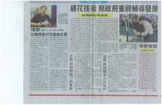
Pic's L to R. My Students in PMC building learning to scrape; The set up of the class-room and a newspaper article about the classes I did for all the CEO's of the machine builders in Taiwan. We did this so the CEO's understood what scraping was plus showed them how difficult it is. A gift I was presented from Taiwanese Machine Builders Assoication (TAMI) on my help to improve their machine industry.:-) Rich
 

Attachments

  • my class.jpg
    my class.jpg
    93.7 KB · Views: 397
  • 1.scraping9464.jpg
    1.scraping9464.jpg
    95 KB · Views: 695
  • rich.news.1.jpg
    rich.news.1.jpg
    97.2 KB · Views: 291
  • TAMI Gift.jpg
    TAMI Gift.jpg
    39.6 KB · Views: 304
Another thing that G&L did was they cast into their columns 3 points on there back side so when they milled, ground and scraped them, they were sitting on the exact same place. You will see that concept being used on Taiwanese machines now :-)
https://en.wikipedia.org/wiki/Bending
.
yes i agree parts needs to be supported on the same spots to get consistent readings. very rare but i have known machinist to send a part that was NOT remachined back to inspection and then inspection remeasures and says it is in tolerance now.
.
just keeping lint, dust / dirt off and supporting consistently it is not easy to get repeatability to .0003" especially when parts weigh over a ton
 
cast iron is not perfectly mixed when poured and definitely has different properties depending on cooling rate. the center of thick sections are softer than the area near the skin which contacted mold when cooling. in the old days they poured a wedge shape and broke with a hammer and could see by the color of the fracture where gray iron and white iron meets. the closer to white iron the harder and stronger but harder to machine. it is quite normal to have different metal characteristics like hardness in the same casting. the different metal types can have different expansion and contraction differences with temperature thus a part can change shape with temperature changes
..... slag inclusions are also often in the mix. a grain of rice size slag inclusion can definitely effect how a surface machines which can effect cutting force and part deflection
 
As I understand it, Airy points in the classic sense refers to separation of two points in a level plane on which a homogeneous elastic bar is supported where the deflection from gravity at the ends equals the sag in the center. Or some such wording hopefully more elegantly expressed;

I was taught in my trade physics class that the Airy points for a homogeneous bar or beam of constant section could be assumed to lie on 2 /9 from each end of its full length (l). That leaves 5/9 for the middle or 0.555l.

The airy points of a camel back straight edge are far different from those of a scraped prism or a lathe bed of non-uniform mass distribution. So Airy points in the real world have to be determined empirically by actual measurement. When precision is required, rote application of proportions can be chancy and works only in idealized beams and bars of constant section.

Many a time I've had a machine bed up on a planer table where I lifted and shifted blocking to get the bed in the freest state possible to determine its neutral/lowest stress condition. A guy could easily spend half a shift juggling a thousandth this way and that not thinking the machine when re-conditioned and assembled would be jacked and leveled into alignment making those careful tweaks unnecessary - that is - close was plenty good enough.
 
As I understand it, Airy points in the classic sense refers to separation of two points in a level plane on which a homogeneous elastic bar is supported where the deflection from gravity at the ends equals the sag in the center. Or some such wording hopefully more elegantly expressed;

The airy points of a camel back straight edge are far different from those of a scraped prism or a lathe bed of non-uniform mass distribution. So Airy points in the real world is situational not mathematical except in beams and bars of constant section.

Many a time I've had a machine bed up on a planer table lifting and shifting blocking to get the bed in a free state to determine its neutral, lowest stress shape. A guy could easily spend half a shift juggling thousandths not thinking the machine when re-conditioned and assembled would be jacked and leveled into alignment making those careful tweaks unnecessary - that is - close was plenty good enough.
.
i occasionally get cnc milling jobs where i measure part and it appears to be within .0003". then inspection marks it up to setup again this spot .0010" higher compared to other spot and i remachine it.
.
i can adjust a cnc gantry mill one column higher than the other easy (Y to Z perpendicularity) but adjusting columns if they are leaning .001" at 90 degrees or the X to Z perpendicularity i cannot adjust easy. just saying for various reasons i have to occasionally remachine .001" taper or it appears to me to be a .001" taper but inspections says it is perfect
.
i have had jobs where part on 3 points and measures flat and they want me to twist it .001" which is not easy on 3 points requires a 4th point, remachine it and when unclamped i measure a .001" twist and they say it is perfect
.
after some time you learn not to question it just give inspection what they say is perfect. thats why i use .0010" and .0012" (.03mm) feeler gage material as shims to get a .0002" difference by shimming. at .0002" tolerance even the oil coating on feeler gage material can easily effect thickness
.
old timers use to say got to watch the fingerprints. they add thickness on the shims you know
 
DMF:

You gotta know how to defend yourself from inspection dweebs. They'll stage precision parts under the space heater then move them onto a cold granite flat or CMM and try to make a liar out of you based on a ten minute scan. Don't be shy about challenging their readings and how they collected them. If they point to their CMM and shrug you got them. Heat and post-machining material stability have made fools out of better people than you and I.

At the same time, coolant evaporation can make a liar out of you. Chasing a thousandth over 10 feet can be heroicly un-productive in terms of actual improvement of part quality.
 
You gotta know how to defend yourself from inspection dweebs. They'll stage precision parts under the space heater then move them onto a cold granite flat,or CMM and try to make a liar out of you based on a ten minute scan. Don't be shy about challenging their readings and how they collected them. If they point to their CMM and shrug you got them. Heat and post-machining material stability have made fools out of better people than you and I.

At the same time, coolant evaporation can make a liar out of you. Chasing a thousandth over 10 feet can be heroicly un-productive in terms of actual improvement of part quality.
.
inspection works in climate temperature controlled area. i question though zeroing to a small 6" length surface then measuring the perpendicularity error of a longer 50" length surface. it amplifies error reading. if zeroed on 50" surface and read 6" surface the numbers are lower.
.
it is a taper per foot thing. .0002" error per 10" is .0010" error per 50"
 
There you go. What's the controlling frame of reference? The concept of "best fit" gets cranked in somewhere. Does the net sum of product part tolerance and geometry readings nest in the plan tolerances? We're making usable parts not perfection. Projecting a small feature in tol readings to reject a 50" feature seems like tail wagging the dog.

I could tell you stories.
 
Last edited:


Back
Top