What's new
What's new

Jafo Jarocin mill repair.

RC99

Diamond
Joined
Mar 26, 2005
Location
near Rockhampton, Queensland, Australia
I was watching some videos on youtube of Jafo Jarocin mills like what I have and noticed they have a rapid travel feature. Mine has a rapid button, but all it ever did was engage the feed motor and move the axis in whatever feed speed was selected at the time. In the videos pushing the rapid button made the axis rapid, then went back to normal feed speeds when released.

So removing a cover and peering into the gearbox revealed an electrical wire heading into the innards. I suspected an electromagnetic chuck, and found where the wire exited from the feed box. I also found a blown fuse, bypassing it made the 24V light work and 24V to this mystery wire when the rapid button was pushed.

I would not normally had done anything about it, but on this mill for some reason the table points up to the moon, so I wanted to fix that anyway. And the knee gearbox was full of crud which needed cleaning out. It is of Russian communist era design, so heavy castings, simple enough design but a lots of hours to get things apart as have to pull things off to get other things off to get the gearbox out.

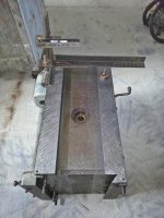
The removed feed gearbox looks like this
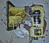
20160310_195518.jpg

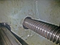
To remove it the z axis screw has to be removed, along with other things due to it's L shape. Upon removal an electromagnetic chuck was revealed. The gearbox splits into two and after much swearing at russian/polish designers of the era the open circuit clutch coil was removed. To get to the clutch a few other things had to be removed that really should not have to be.

The coil was epoxied in so I cooked it in my heat treatment oven until the epoxy decomposed and the coil revealed. The clutch is a Stromag ER5 24V 37W. I was intending to try to make the coil myself, but I have no coil winding machine and a shop in town has done these before so they did the coil for me.

All I had to do was clean up the epoxy a bit as they made it a bit too proud. Testing on 24V reveals it works.

the old coil
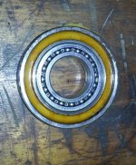
20160311_211056.jpg

Epoxy cooked out revealing the coil itself

20160312_100908.jpg


repaired

20160318_162053.jpg

In the process of putting the gearbox back together.

Which leads me onto finding out why the table points into the air.

With the knee stripped but still on the machine, putting a square onto the knee butting up against the column reveals the problem is not there.

So are there is some minor wear on the knee ways I will scrape them in again.

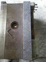
I have started with one flat way and here is a pic half done.
20160317_140731.jpg

It only took half a dozen passes to get this far and another four and it was done.

Now working on the little guiding ways, then make the other flat way parallel to the finished one. Doing it this way as there is very little to scrape off. it is not worn much at all. Will describe a different way further on.

I have had to grind up a skinny steel straight edge to do the guiding ways. Slideway grinder was interesting to work, there is a 0.0002" bow I could not grind out. The grinding wheel would grind on the ends and just dust the middle which an indicator said was a 0.0002" rise on the ends, but I could not grind it out. Just more things to learn how to do I guess.
 
I got the gearbox back together and it has been cleaned and wrapped in plastic. Incidentally that plastic sheeting you put under concrete before you pour it makes good material to wrap things up in.

It is an interesting design. The bronze crossed helical gear you see here spins all the time and it is connected to the lubrication pump and the electromagnetic clutch. So when you press the rapid button and the clutch engages, power is fed through this gear to the axis's being moved.

The worm wheel you see next to it is connected to the gears that selects the various different feed rates. Now the bronze worm wheel has an overrunning clutch of some description affixed on the inside of it. So when the rapid is engaged the worm wheel keeps going at the same speed but the overrunning clutch lets the shaft spin at rapid speed.

20160319_125934.jpg


Here is the mating gearbox that contains the gears that select the various feed rates.

20160319_125440.jpg


Joined together again


20160319_141207.jpg

Onto scraping now.

To spot the small vertical shears that guide the saddle I reground my steel straight edge that was made out of 75X20mm flat bar. I had milled the top of it and warped it a bit. So I slideway ground it but could not get a 2 tenths bow out of it. So I scraped it flat. Although steel is not fun to scrape.

20160319_172647(0).jpg


Really the guide way is not worn badly, only a 0.02mm difference between the ends and the middle. Pretty quick to bring back to flat.

Getting there

20160319_173319(0).jpg
 
Here is the finished skinny guide way. It is parallel with it's mate.

I measured it with a micrometer and gauge blocks as we all know a scraped surface is not actually flat flat and a micrometer on it's own will not give a good ready as at some point you might be in a scraping hole and another point on a high spot.

20160320_074214.jpg 20160320_073804.jpg
 
Now I am NOT doing a proper rebuild nor even a proper scrape. I know I should be scraping the column and spotting against that. But as there is little wear in the machine I am just tickling things up a bit. To be brutally honest I could have got away with just a flake of the slides.

If the machine was proper worn I would be going about it a different way, the proper way.


All the top slides are done. If you were doing it with a kingway type device you would do it the following way.

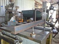
Scrape the flat horizontal way flat, then scrape the outside vertical guide way flat. Then assemble your kingway type device as per the photo and put it on those two ways adding a bit of oil to them to make it slide easier.

20160320_111727.jpg

Slide it to either end and take note of the reading. Is it way way more then you expect like I found. Put some weights on the other end and see what it does.

20160320_104921.jpg

Low and behold you find out your work-piece is not stable.

Make it stable and continue on.

So I made it stable and scraped the mating horizontal way flat and parallel.

Then to check the parallelism with the inside vertical guiding way I put an indicator on as shown

20160320_112041.jpg

That checked and done I turned my attention to the dovetail way.

A mild initial scrape and check squareness. Really you want the nose pointing up something like 0.02mm over 500mm.

20160320_150642.jpg

The wide dovetail slides are finished and flaked. Just have the dovetail to tickle up a bit.
 
So what was the ultimate source of the knee misalignment, just wear on the multiple ways?. My Jafo has one way oiler on the knee that is so badly blocked that I suspect the hole is not drill through the iron to the ways, now would be the time to check such things. Thanks for the tutorial
 
Not sure yet, just getting the knee done and then will reassemble, then move onto the lower saddle section that has the swivel joint, then there is the upper saddle section and lastly the table itself.

Of course they are all heavy pieces, too heavy for lifting by hand.
 
Nice work RC.

Had to chuckle though :D
Low and behold you find out your work-piece is not stable.

How bout using another level as a base level, to keep an eye on work movement. Looks like theres plenty of room around the Kingway, then you know your eggs are eggs.
 
Last edited:
That is a good idea. Although it probably should have gone onto three blocks of steel.

I got all the knee finished tonight.

Bit disappointed with how the gib turned out.It will do but not up to how I would like it.

Guess what material they made it out of? Mild steel of all things. So while scraping it I got a million and one super sharp splinters, and said bugger it, that will do.

sparkle sparkle.

20160321_185612.jpg
 
Yeah defo on 3 points of something hard. Maybe turn up 3 shallow cones just for that purpose is an idea.

I remember struggling with steel. Everything I tried towards push scraping just dug in and created a very nasty burrs. I found a pull and scoop type effort, so the stroke doesnt finish in the work helped alot. A lot easier to stone and seemingly less of it ended up in my hands.

Wow, theyve actually milled the central relief in that knee. No messin!
 
Knee is back on, it is pointing up a smidgen. With the square butted up against the column I can just see a bit of light shining through the square down the bottom.

I put the lower saddle on and it's squareness to the column is good also. I have to scrape it in next. Although I will probably reassemble the knee innards in the coming week.

20160322_142528.jpg
 
Now I am NOT doing a proper rebuild nor even a proper scrape. I know I should be scraping the column and spotting against that. But as there is little wear in the machine I am just tickling things up a bit. To be brutally honest I could have got away with just a flake of the slides.

If the machine was proper worn I would be going about it a different way, the proper way.


All the top slides are done. If you were doing it with a kingway type device you would do it the following way.

Scrape the flat horizontal way flat, then scrape the outside vertical guide way flat. Then assemble your kingway type device as per the photo and put it on those two ways adding a bit of oil to them to make it slide easier.

View attachment 166365
I would not have the level vial up so high as it will multiply the error ay up there, unless you do that on purpose because your vial spec is high. The real KW uses .0003" / 12".
No need to use the other vial if you are checking it with a straight-edge. I would also recomend using a surface plate to keep the flats the same height and parallel and double check with KW. OH nice shoe in the 9th pic....lol...must be a Aussie open toed work shoe...? :-)

Slide it to either end and take note of the reading. Is it way way more then you expect like I found. Put some weights on the other end and see what it does.

View attachment 166366

Low and behold you find out your work-piece is not stable.

Make it stable and continue on.

Put the knee on 3- points and it won't rock plus if you place them at 30% or Airy points, what you prefer, you will be assured the knee doesn't bend low in the middle if supported on the outside edges.

So I made it stable and scraped the mating horizontal way flat and parallel.

Then to check the parallelism with the inside vertical guiding way I put an indicator on as shown

View attachment 166367

I rest the indicator on the surface and read high and low spots. I also use a .0005" indicator so it doesn't bounce like a .0001" indicator does. that way you can slide the KW along steady and once you get good, no need to use the gage block.

That checked and done I turned my attention to the dovetail way.

A mild initial scrape and check squareness. Really you want the nose pointing up something like 0.02mm over 500mm.

View attachment 166368

The wide dovetail slides are finished and flaked. Just have the dovetail to tickle up a bit.

i see you put the knee back on, next time grind another oil grove opposite of the single one you now have. More lube the longer it will last.
 
Last edited:
I'm a bit disappointed in this picture. :(

166708d1458643642-jafo-jarocin-mill-repair-20160322_142528.jpg


There's normally a wild Brahman Bull or a Kangaroo in the background.

R.C sent me a Pic, not long before Christmas. I don't think we have seen it here yet? He had a family of Camels strolling through the 100,000 acres that are his back yard. I don't seem to have that Pic on my lap top at home. It was pretty cool.

Regards Phil.
 
20151207_145349.jpg

Here is a picture of the spiral gear that makes the z axis go up and down.

The result of coolant ingress into the knee area. While the gears, shafts and bearings are mostly in good condition there are definite signs that the knee has been full of water based coolant and sat like that for an extended period.

20160325_164148.jpg

lube system working

20160325_195808.jpg

Thanks Richard for your post above, and yes those shoes are currently open toed :) The steel cap fell out a fair while ago and I was made redundant on the job I had that required me to wear steel caps, so no need to replace my shoes just yet :)
 
Getting there.

I would not want to put any more thickness blue on the master. You can see it just starting to smear however it lets me look into the future so to speak to see how flat it is overall, and really shows the deep holes.

20160327_104031.jpg
 
Been dabbling a little bit with it.

Had to wait on an opportunity to get some oil seals. Which I now have got. I have pulled apart the little right angle gearbox that transfers the feed from the knee to the saddle. It also incorporates the saddle cross slide nut.

Inside the box is just a set of spiral bevel gears. It should contain oil, but it had all leaked out, but the bearings and gears were all good. It has two oil seals on the horizontal shaft but they had a wear groove in them. it was not deep and I had new seals so I ground out the groove on the OD grinder. Did not take much. A little trick someone told me awhile back with oil seals if you have a groove or a slightly smaller shaft to seal is to remove the spring on the seal lip, undo it, shorten it a bit with some side cutters, them screw it back together and put it back on the seal, that makes it put a bit extra pressure on the lip. I took about about 2mm off the spring on a 35mm ID seal.

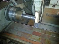
Here is the grinding going on. I have a magnetic chuck in the workhead, which has a 3 jaw chuck stuck to it, which holds the workpiece.

20160401_170624.jpg

same setup showing the groove being ground out

20160401_171519.jpg

For those that have never undone a lip seal spring, here is what one end looks like. Of course as you know, you cut the other end off to shorten.

20160401_174116.jpg
 
The more I do the less I seem to accomplish.

I have got the feed transfer gearbox back together and installed. It incorporates one of the underside saddle retainers (or what ever is the proper name), which I ground to close up the clearance to about 0.0005"

20160402_115714.jpg

I also scraped the saddle gib and guess what? It was steel as well.

I had always had trouble the the saddle cross feed engagement so I decided to fix that while it was in pieces. That took longer then expected. Essentially the shaft that moves a spline to engage the dog clutches was binding. The mechanism is a real silly idea and the later models did away with it.


Went to put it all together with a new seal and of course in fantastic Russian design, the seal does not even go anywhere near the housing.. It just sits there floating in air. You can just see it in the photo

20160402_194257.jpg

I have a fix in mind, but it is a real PITA.
 
The seal discussion reminds me of something I encountered somewhere around 1969 - 70. I was replacing the front seal on a Mercedes differential and looking at the surface the seal rode on. Instead of a plain ground smooth surface, the striations were all diagonal. It must have been a second operation and my surmise was that someone thought all those tiny grooves, oriented the right direction for normal rotation, would have the effect of sweeping oil particles back into the case. Dunno whether that actually works, but I dutifully sanded some new ones through the polished line left by the old seal.


Back
Top