What's new
What's new

Knee way, knee gib, tolerances and operation

xavier2089

Plastic
Joined
Nov 29, 2016
Hi all, first thread but a long time reader (from Adelaide, Australia). Hopefully this post is in the right section.

I have searched this forum but could not come up with the exact information/ answers so if I have missed it, please advise me.


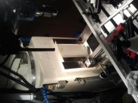
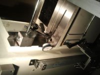
To start with the problem: I have a brand new Taiwanese turret milling machine (similar to a Bridgeport) which was jumping in the z-axis (knee).


After trying to adjust the knee gib (taper type with locking and adjusting screw) the best I could, I was getting about .002 inch movement (with a dial indicator set up on the y way of the knee to the z way on the main body of the mill) moving the knee up and down by hand and even a little more movement using the knee power-feed. The Youtube video below at 12 minutes and 30 seconds shows the dial indicator set up if it is hard to picture.
Milling Machine Maintenance: Adjusting Gibs and Ways - YouTube

In the video, the author, Keith, checks the knee gib adjustment by checking for play with the mill stationary and trying to move the table (with x and y slides locked) by pushing/pulling, etc., which the tolerance he states for his mill (according to the manufacturer) is to be .0003 inches or finer.

My supplier could not get the specs on what the tolerances are to be (they tried contacting the manufacturer but I am guessing language barriers have made this difficult).

So my questions are:

Is the stationary test the only test needed for the proper adjustment of the knee gib? If so, I would imagine that the tolerance for my machine should also be approximately .0003 inches of play?

Is it normal that I get the .002 inches of dial indicator reading when I traverse the knee up and down? I imagine that this could be due to the deflection/ transfer of weight or flex in the knee body?

I take it that the knee lead screw backlash has no significance to the readings I am getting?

Is the knee supposed to slide under its own weight and ride along the top of the lead screw thread or is it supposed to be pushed and pulled by the lead screw?

Is it easy to over-tighten the gib lock screw which can cause bad readings?

I apologise for all of the questions however it is very frustrating not knowing whether the machine is within tolerance or not (I am aware that the quality of the machine is not first class so to speak) and why it may not be within tolerance.
If the .002 inch deflection is normal then I will have to be careful when backing out of work I guess.

Any knowledgeable help would be greatly appreciated, thank you,
Xavier
 
Keith is doing it wrong....He will be updating that video in January after he takes a class he is hosting. The knee should fall and not be pulled down. Checking the Z gib should be done the same wa at he does the table and saddle...from the side. Mag on column, .0001 or .0005" indicator on the knee. Even with the top of the gib. The way he has his set up he is multiplying the error...reaching out there like he is. The indicator should be set at the ends of the gib on the outside of the way.

You need to have .0003 per side or a total of .0005/6" if the machine is new and was done right. You having .002" could change depending on where you have your indicator mounted. But I would rather see .001" or .002" then .0003". You need to have a thin film of oil in there to lube the ways.

If your machine has Turcite on the ways and gib then a smaller amount won't hurt.

It's late here (2 : 18 AM) .... check it out and we can write (chat) later. Rich
 
Sorry for the late reply Rich, my internet has been down and I needed a new modem.


So the dial indicator is to be on the gib itself? And is to be checked on the bottom and top of the gib?

Below is a link to some pictures:
Xavier Gates (@xavier.gates.9) • Instagram photos and videos

So the correct location for the dial reading is in the below picture (with a test type indicator would be more appropriate obviously)?
Instagram


So a static test only is to be done (for gib adjustment) in which one pushes and pulls on the bed to check for play. My mill is new and has no Tercite coating on the Z ways. Therefore I should read 0.0003 inches of total play with the indicator on the top of the gib and 0.0003 inches of play in total at the bottom of the gib?

And locking the ways may cause some movement but this is irrelevant to gib adjustment?

Thank you Rich,
Xavier
 

Attachments

  • 2016-12-05 18.02.49.jpg
    2016-12-05 18.02.49.jpg
    38.2 KB · Views: 367
  • 2016-12-05 18.03.03.jpg
    2016-12-05 18.03.03.jpg
    36.6 KB · Views: 461
  • 2016-12-05 18.07.10.jpg
    2016-12-05 18.07.10.jpg
    94.7 KB · Views: 395
  • 2016-12-05 18.07.16.jpg
    2016-12-05 18.07.16.jpg
    33 KB · Views: 482
  • 2016-12-05 18.13.18.jpg
    2016-12-05 18.13.18.jpg
    96.3 KB · Views: 321
I must be getting old and crabby. I am getting real tired of answering questions like this.

If the machine is new, why are you screwing with it anyway? You HAVE to have room for oil or the ways will "lap" together and it will scratch and you will get a gall. .0003 to .0005" per side of the column ways. Meaning left side and right side, not top and bottom of gib. Top and bottom should have the same reading . I would set the Z (or up and down) at .0008" to .001" side to side movement. You can move the table out and press down on it check indicator. Then move table in the opposite direction and press down...As I said I would rather see .002" total then .0003" total.

When you are cranking the knee up and down always stop the movement going up. So if you move the knee down, go past where you want to go and crank it up, so weight of the knee is on the screw and nut. Then when you reach where you want to be lock it. Next move unlock the Z and move it.

A tip, slide a piece of paper between the mag base and ways, so you don't scratch the ways.

I am sorry, as I see your excited to be a new machine owner. If the machine is new and you start to dink around adjusting everything. Think about buying a new auto and you take off the carburetor and start turning screws just to see how it works. Seems a bit dumb doesn't it? The forum is here to answer problems with worn machines. Not brand new machines because you have a new machine distributor to ask and if the machine is new, it probably has a warrantee and you dinking around with gib adjustments you may have voided your warrantee.
 
Those pictures (which I have now removed) with the indicator on it were just for reference point of where to position the end of the indicator.

I really appreciate your help on this Rich, as so far, the information you have given me is the most comprehensive on the internet from what I can see.


The reason I am mucking around with the new machine is because it was sticking on the z axis. When I rang my supplier, their technician didn't have a clue what sort of readings on the machine should be taken. The service manual said to tighten the gib until a slight drag is felt. This to me was insufficient and could have large discrepancies.
I rang the major supplier in Australia and they had no information on the matter. They tried contacting the supplier overseas but due to language barriers (I am guessing) they were of no help either. They also had no idea about what tolerances it was to generally be within.
Even in that video in the first post, you mentioned Keith was doing it wrong so I imagine it is a procedure few would know how to do correctly.
So rather than deal with suppliers that don't know what they are talking about and are of little (if any) help, I would prefer to get the right information from someone like yourself.

As you mentioned, hopefully I have not damaged anything.


If I am not mistaken then, the correct procedure/ set up for knee gib adjustment is as follows:

With the indicator set reading the side of the knee like in the images below (only for top reading):
Xavier Gates (@xavier.gates.9) • Instagram photos and videos
One should aim for " .0008" to .001" side to side movement "
The same clearance should be obtained with the indicator on the side at the bottom of the knee.

"(each column way needs .0003 to .0005 clearance)"


Thank you once again Rich, your sharing of knowledge on this is extremely appreciated. I'm sure other people will benefit from this as well.

New to me also was your following point:

"When you are cranking the knee up and down always stop the movement going up. So if you move the knee down, go past where you want to go and crank it up, so weight of the knee is on the screw and nut. Then when you reach where you want to be lock it. Next move unlock the Z and move it."

After having a dial on the face of the knee way, it can be seen how important this is to do.
 
I just set the knee gib so when it is lubricated it does not chatter going down.

I do not think I have ever done any measuring ever when adjusting any gib. I am probably doing it wrong but for me it is all about feel.
 
Thanks for the replies JS and RC99. Cheers for the link JS, I will get a copy of the book- it has excellent reviews.
 
It might have excellent reviews but it is not a very good book. It is just nearly the only one of it's type.

Or to put it another way. Think of the worst car you can. If that car was the only car in existence, it would still be better then a horse and cart and thus get excellent reviews.
 
I probably should clarify, I do not think MTR is a bad book. I just do not think it a well written book for the layman. I still have a copy and I did get some things out of it. But I have got a hell of a lot more out of reading threads on forums, especially the forum threads where people have done successful full and complete rebuilds on machine tools.
 
When you are cranking the knee up and down always stop the movement going up. So if you move the knee down, go past where you want to go and crank it up, so weight of the knee is on the screw and nut. Then when you reach where you want to be lock it. Next move unlock the Z and move it.
Say a brand new mill was set up properly. If one were to bore a hole with a boring head, would the quill feed produce a more accurate hole (hole dimensions such as parallelism, squareness, etc.) than the knee feed?

I imagine that when backing the cutter out of the hole, the cutter would leave a deeper groove using the knee than the quill (because of the different loads on the knee causing deflection)?

Ie. Would there be more chance that the cutter could slightly wonder with the knee feed because of the play? Or are the tolerances of the quill about the same?
Or does the lack of rigidity of the quill being extended cause greater inaccuracy than the knee?

After doing a little looking around, it would appear that jig borers use a quill as opposed to any slide ways. Some engine boring machines appear to use a slide way though.

From practical machinist forum posts, they always say that it depends. Obviously the quill travel has its limits. But as far as good practice goes, it would appear that it is best to use the quill for as much as possible, not the knee???

I know this is slightly off topic and that there are forums up already about this but none have a definitive answer.

There is no definitive answer. It all depends on the machine, the operator, and the application.

DeVleigs for instance have an extremely accurate quill that is incredibly expensive to build or rebuild yet holds tenths at full extension.

Compare that to a really cheap Chinese drill press quill from a big box store. You will be lucky that you can hold low hundredths at a couple of inches.

Both are quill feeds but basically in name only. Completely different way the the two are built.

Now in your example of a turret mill and say for instance that you are desiring to bore the most accurate bore possible on your machine, then assuming that the quill is at least of reasonable quality, the quill will be most accurate.

Your approach seems to be that you falsely think that tightening your gibs to the least allowable movement will maximize your accuracy. This is not how you should be thinking about this.

To do a precision bore you would want to get the part into position. Then you would want to verify the head tram to table in both X and Y. You would then feed the quill for the bore.

If you were to use the knee for the Z feed, you would be adding the knee axis deviation to your quill deviation. So in this case you could potentially double or more the minimum deviation of your machine. Each axis that you move and lock adds to the total possible error

Machines such as jib bores and jig grinders are designed to minimize these issues, making them expensive.

It is also important to understand that a very skilled machinist that knows his machine, even though it might be very loose, will produce a more accurate bore compared to the novice using a new machine that does not understand what he is doing.
 
Ziggy give me a fricking break, we are talking about a Knee mill (see the pictures)and any good machinist always cranks it up so the backlash is removed from the screw and nut. The weight is pushing down on the nut.
 
Richard,
You completely missed my point. The OP was originally concerned with the his gibs being too loose on a new machine. Then he asks about what is more acurate way to feed for a bore.

Yes it is a turret mill with all of the deficiencies that we all know exist in it and it is not the best machine to use for tight tolerance work.

The OP then asked about why no one would give a definitive answer on which method is more accurate.

From my perspective any time you are trying to do anything precise on a turret mill, the less you move the knee, saddle or table, the better off you will be in absolute positioning of the part. Everything moves on them and repeatability is not what I would call great.

The OP is obviously a newbie and does not have an understanding about what actually determines part and location accuracy.

Are you under stress or is it the time of year because you seem to be unusually edgy. I hope you are doing alright.:)
 
Thanks for the reply Ziggy2.

There are so many details to what is good practice that I would guess most people (including experienced machinists) miss. The amount of people on the other forums who were 'taught' to use the knee for boring instead of the quill is surprising.

I would completely agree that "any time you are trying to do anything precise on a turret mill, the less you move the knee, saddle or table, the better off you will be in absolute positioning of the part."

You guys have taught me a few tricks for better accuracy:

Use the quill over the knee wherever possible if it is a decent machine (I was doing it the other way around before)

Always take the backlash out of the knee- all of the tramming videos on Youtube never mentioned this to my recollection, nor was it in any of the books I have read.

"It is also important to understand that a very skilled machinist that knows his machine, even though it might be very loose, will produce a more accurate bore compared to the novice using a new machine that does not understand what he is doing."

Ziggy2, could you please explain the above comment in some detail? I have heard other people say this as well and am curious as to why this is so.
 
"It is also important to understand that a very skilled machinist that knows his machine, even though it might be very loose, will produce a more accurate bore compared to the novice using a new machine that does not understand what he is doing."

All mechanical devices have assorted types of unwanted movement.


We have: mechanical resonance, structural deflection, off axis motion on each axis, backlash of mechanical driving forces, heat distortion, and probably some I haven't thought of.

All of these motions interact with each other and ultimately determine the precision at which we can make a part. The high end machine tool builders go to great extremes to minimize the effects of these motions.

The experienced machinist and especially the one that knows his machine, will know how to compensate with his technique and sizing to get where he needs to be. How the machinist clamps the part is also a key component in controlling these issues.

For your question about boring on a turret mill a lot of this gets back to simple geometry.

Let's take the knee motion for instance. The knee moves up and down in the Z axis and we can use the knee handle dial to tell how much we have fed the part. Outside of screw wear we have a very linear travel measurement.

The part that is difficult to precisely measure without going to extremes is how the off axis motion of the knee affects our bore. The Z off axis motion shows up as X and Y motion at the part in relation to the spindle and this is assuming that the saddle and table are properly locked. Usually the movements are small and really aren't an issue for turret mill work.

These off axis motions also are not perfectly inline with the axis layout, so this induces a degree of off axis taper into the bore.

For the average person, this is way more than they need to apply but it is good to understand how all of the motions interact and translate from one axis to another.

Knowing and understanding these motions allows the experienced machinist to "adjust" the numbers to compensate for the induced error and make the part within spec.

This is why there is such variance opinions on technique and opinion on how to do things. One method might work very well within a limited tolerance range but can not be applied for work requiring any tighter tolerances. Another technique might allow for very tight tolerances but is very awkward and time consuming for most jobs.

This is why you get the answer, "It depends."

Same type of question on which is the best way to measure things. If we are framing a house, a good tape measure is the appropriate measuring tool. If we are machining small aerospace parts, then a good micrometer is probably the appropriate tool. Neither tool scales well to applications outside its designed purpose and so it is with machining techniques.
 
I have to ask this. While setting my gibs, per Richards way. I notice that the gib moves every so slightly when I move the table to the right, stop and move it to the left. If the gibs are set correctly, should the gib move at all?

The x axis gib has.0007-8 of slop and the Y is about the same. This is on a Bridgeport.

Yes, that is normal. If you go tighter, then you will not have room for the way oil film to lubricate the ways. That leads to accelerated wear and scoring.

Richard mentioned this in this thread.

And by the way, Richard's method is accurate. Some of the other methods really aren't accurate but the indicator doesn't tell you that because of flawed geometry in the method.


Back
Top