What's new
What's new

Lathe adjustment and checking..

tmmill

Plastic
Joined
Nov 9, 2009
Location
california, usa
What is the best or acceptable method for checking the alignment of a gear head lathe to the tail stocks and ways? Not just the tail stock offset adjustment but the entire headstock alignment and height using the incorporated limiting and locking bolts for side to side and angular adjustment? I haven't been able to find much guidance on this procedure.

thanks,
tony
 
I'm looking and I think I found that one and a couple more. There goes the afternoon at the beach with the dog.

Thanks.

I presume an accurate test bar is important. I know I am probably being naive asking this, but on Ebay there are ground test bars from India. They claim accuracy of 2 10ths. Has anybody bought one? I am probably dreaming that I can get a good ground test bar for $110 bucks, but I WANT to believe it:rolleyes5:

Scott
 
To know the head is square to bed you might have a test bar and with a flat indicator point run down the test bar front face...And along the top. Might run indicator to the chuck side to get a rough idea (short) the head is square to bed with not having a test bar..Not likely the head stock is out of angle/square to the bed unless it was dropped or the like.

You might turn the test bar with the spindle to be sure the machine taper is bug free.. and runs true.

A straight bar with centers can tell the top and face check are straight.

Head to tail you can OD turn a slug in the head end to the same diameter as the tail barrel .. then compare the top and the face of the slug to the tail barrel..Yes try it at a number of places along the travel.

*Really have to watch out with using a test indicator because running down a diameter you can see the angle of error and the going above and below center, so getting false idea and adjust in more error.

You can mount an indicator to a turned slug in the head stock and then turn that around the tail barrel.

The tail to head stock is important to center drill a part, and to turn a straight part.

Still a lathe check may not be exact all along travel due to wear places in the bed so the tail may go up and down a few thousandth along the way.. So the part is the final check.

On a grinder one might measure the part at both ends. Put the part in the machine between centers...Then come into just touch with the wheel to find zero/zero dial on a straight part or the same dial number error as the part error. Then adjust away half the error.
 
Test bars are nice if you have one and it's straight over its length. But they are not always perfect, expensive, and, once used, seldom needed, if ever again. Personally, I advocate the "two collar method" which has been cussed and discussed extensively on this forum.

If you happen to have a straight smooth diameter material accurately centered you an mount it between centers and scan its length to determine quill axis alignment in a vertical plane and tailstock offset in the horizontal.

Alternatively, turn a short piece of remnant material to the precise diameter of the tail stock quill. Extend the quill a few inches. Mount an indicator on the tool post and scan both diameters from a single setting. If the lathe has any wear, chances are the quill will register low but the lateral (taper adjustment may be set to any accuracy you may require.

Tramming the quill diameter with an indicator mounted on the spindle may lead to error because of deflection. A DTI mounted 5" from mag base or a clamp sags 0.005 to 0.015 depending on the number and size ot rods and snugs employed. Proceed with caution

A 1 1/4 dia test bar 12" long sags 0.00035" at the end; a significant fraction of the traditional tolerance. The sag error apparently doubles as the set-up rotates top to bottom. See Rich King's Richard King demonstrating indicator sag. - YouTube or Stefan Gotteswinter's Machineshop Physics: Indicator sag - Durchhang von Messstativen - YouTube excellent indicator demonstrations if indicator sag .

Remember every thing is made of rubber and horizontal rotating axes pose particular problems in establishing accurate alignments.
 
Last edited:
Test bars are nice if you have one and it's straight over its length. But they are not always perfect, expensive, and, once used, seldom needed if ever. A 1/4 dia test bar 12" long sags 0.00035" at the end; a significant fraction of the traditional tolerance. Personally, I advocate the "two collar method" which has been cussed and discussed extensively on this forum.

If you happen to have a straight smooth diameter material accurately centered you an mount it between centers and scan its length to determine quill axis alignment in a vertical plane and tailstock offset in the horizontal.

Alternatively, turn a short piece of remnant material to the precise diameter of the tail stock quill. Extend the quill a few inches. Mount an indicator on the tool post and scan both diameters from a single setting. If the lathe has any wear, chances are the quill will register low but the lateral (taper adjustment may be set to any accuracy you may require.

Tramming the quill diameter with an indicator mounted on the spindle may lead to error because of deflection. A DTI mounted 5" from mag base or a clamp sags 0.005 to 0.015 depending on the number and size ot rods and snugs employed. Proceed with caution

Remember every thing is made of rubber and horizontal rotating axes pose particular problems in establishing accurate alignments.


Looks like a typo there - " A 1/4" dia test bar 12" long ". Surely that should be an 1-1/4" test bar.


To the OP- This subject has been discussed previously at massive and prolonged length. Any search of the site will give you a full evenings reading materiel. I've had more than my say in the past so I'm not going to bother again.

I'm a test bar fan myself. Schlesinger recommends the use of a test bar, that'll do for me.

Regards Tyrone.
 
QT: Forest [Tramming the quill diameter with an indicator mounted on the spindle may lead to error because of deflection.]
....and because close to the head stock may be where the most bed wear is....So down the bed it may be different.
 
QT: Forest [Tramming the quill diameter with an indicator mounted on the spindle may lead to error because of deflection.]
....and because close to the head stock may be where the most bed wear is....So down the bed it may be different.

You're right about bed wear. OTH, nope. Overhang is overhang. Stiffness increases as the square,of the solid section for a constant length. Cantilevered deflection increases as the cube of the overhang for a constant solid section. Try it see.

Sometime when you feel like experimenting, duplicate the Richard King/Stefan Gotteswinter demonstrations using your most rigid indicator set-up.

Another experiment is to test the rigidity of the snug supplied with your indicator (AKA clamp.) Determine your indicator's center of mass, construct a balance (using a pencil for a beam and 3 lb fishing leader for a suspension.) Balance the indicator (using washers for weight) on one end to counter-balance the indicator on the other. Cook up the most rigid indicator mount within your capability. Mount the indicator and arrange one leg of the balance suspension on the indicator's center of mass. Set a zero to a horizontal reference surface. Take a reading with the balance in effect and again relieving the counter-weight so the indicator mount has to support the weight of the indicator. There will be a difference sufficient to suggest even the most rigid indicator snug exhibits some deflection and thus verifies nothing is immune from gravity..

Everything is indeed made of rubber
 
Last edited:
The Holy Crap! Moment

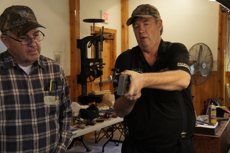
A picture is worth thousand words and could be an inspiration for you to repeat this experiment at home:
NEX_5_DSC3211.jpg


That has been an eye-opener moment during the class.

Paolo
 
I'm a test bar guy. They are NOT expensive and if you can afford owning the lathe, you can afford the mating test bar. That said, and the machine is setup and square at installation time, the question comes on how often and when should alignment be rechecked. The correct answer is, when doubt arises. With a test bar and a precision level, the check is fast and convenient. When I installed my heavy L&S, I did it initially and rechecked weekly for a month until the machine finally settled in its new location and I had it mounted on an 8" thick concrete pad, which was recommended by L&S. On smaller lathes, settling is not usually an issue.
 
What is the best or acceptable method for checking the alignment of a gear head lathe to the tail stocks and ways? Not just the tail stock offset adjustment but the entire headstock alignment and height using the incorporated limiting and locking bolts for side to side and angular adjustment? I haven't been able to find much guidance on this procedure.

thanks,
tony

I haven't read all the other posts but from my experience the first thing to evaluate lucidly is if it's worth the trouble. The business of a lathe is to turn round. If you need taper-free over some substantial length you'll need a cyl grinder. For most common work negligible taper over some 2" is all that's realistically needed. The most workable method is the two collar one because it averages a couple of nasty errors very hard to account for otherwise. The test bar method works fine and is quick for new machines and new test bars. The most minor seating error of the test bar and it's all down the drain. The best method is to compare the squareness of a freshly faced face-plate with a standard of some sorts. That one is bullet proof but tedious if it's to account for the errors in the ways.
 
I know I am probably being naive asking this, but on Ebay there are ground test bars from India.

I bought a couple, one with a MT2 and the other a MT3, seem to be OK except that they aren't made to the optimum design. Connelly said they should be taper bored or in taper steps, then hardened and ground. It's not natural to the senses to think of a hardened bar of steel sagging but it's a fact of nature, the tapered bore gives maximum stiffness plus the loss of useless weight helps too.

What we need is a spray can of gravity neutralizer. Somebody get to work on it.

An employee of mine was once recalling his experiences working at Boeing, and I went along with it up 'till he told us about "a room they with no gravity we worked in". I asked him if he meant inside the cargo plane they simulate zero G's by flying the apogee and he said "no, it was in their plant".
I should have turned away and let it go, as when I tried to explain physics to him he accused me of calling him a liar, I thought for a second it was going to turn into a fight.
 
I haven't read all the other posts but from my experience the first thing to evaluate lucidly is if it's worth the trouble. The business of a lathe is to turn round. If you need taper-free over some substantial length you'll need a cyl grinder. For most common work negligible taper over some 2" is all that's realistically needed. The most workable method is the two collar one because it averages a couple of nasty errors very hard to account for otherwise. The test bar method works fine and is quick for new machines and new test bars. The most minor seating error of the test bar and it's all down the drain. The best method is to compare the squareness of a freshly faced face-plate with a standard of some sorts. That one is bullet proof but tedious if it's to account for the errors in the ways.


How is the squareness of a face plate going to help you align your tailstock to the bed ? With a test bar you can align both the headstock and tailstock equally.

Regards Tyrone.


Back
Top