What's new
What's new

Stanko semi overhaul

Lumberjack

Hot Rolled
Joined
Jun 3, 2006
Location
Sweden
Hi,

Thought I´d share a little update on my lat(h)est project.

It´s my old stanko 1a616. I asked a few questions previously regarding the treatment of hard beds by means of possible scraping and grinding and gotten many good advise along the road. Short background on me in this context of this is a year ago I never held a scraper. However I was a bit interested and was planning to take the scraping class in Norway in 2014 but missed it but when it came about in 2017 I was informed and could not resist to join. It was great week of good fun among likeminded people. So during this winter I decided that, after lots of practice in the workshop and a local scrapefest hosted in Norway, it was time to take on the lathe.

The lathe is stout being a 13” swing x 27 in centredistance weighing in at 1500kg / #3000. Bed is nearly 2x centre height and the sadle wings are approx 21” wide. Also the crosslide has reasonable dimensions. The 4kW motor generates a speed range of 9-1800 rpm and max allowed torque on the spindle is approx 600Nm peaking at about 30-40 rpm as I recall. These factors made me both buy the lathe and use it for my home workshop needs for about 10 yrs now.

After taking the scraping class and learning lots more about inspecting and measuring machine tools I started realising that Hmmm, maybe there is a bit to work on lathe itself... However main issue during use was related to parting of, that was never easy. But the vibrations were hard to find out exactly where they came from. Some of the common tell-tale-tests such as tapping the sadle wings or prying shimstock into the slideways.

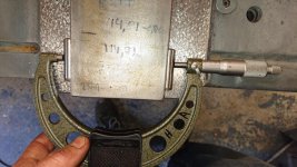
The bed wear I have made representation in a 3D model you can see and the measuring protocol, I could hardly believe it was that much. I mean, I had used it fairly sucessfully albeit being an ameatuer. I believe I can thank the inherent geometry of the lathe for compensating alot of the wear, it also gives me hope the lathe will be working nicely once completed.

Status right now.

Bed is completed, might refine surface of the flat ways a bit further while I´m working the carriage and crosslide.

I´m working on the crosslide now. Top surface was ir-regulary out of flat, both around the T-slot but also other mysterious shape... Thick on left side etc. I thought it was maybe bent first, but no. Thick it was. Underside was actually rather ok, just to scrape straight down really. So top & bottom is roughed in at the mooment.
The sides were slanted in both directions by tenths - of a millimetre! First side I scraped in, about 0,2mm along (12”) and across the height (1 ½”) also 0,2mm. I took that as scraping practice but for the other side I had the mill "talk to it" in the afternoon today.

The carriage / saddle, I´ve made initial measurements on it and while having proper signs of wear it appears main geometry is a not too far out ok, within scraping distance. I guess it was out of geometry from the start and the wear is uneven and still it looks ok, mainly relating to the relation between the bedways and crosslide ways. Next step here is to drill & mill connections, channels and oil grooves needed to install a one shot lube system and fit the crosslide to it.

Being an ameature I mainly post this here to share that your advises come in to use and I really appreciate comments, questions and input.

What intimidates me most right now after having negotiated the bed is actually the tailstock as the bed has come down approx 0,06mm and after scraping the sliding surfaces of the tailstock that one will also come down a few hundreds of a mm. And that´s where my thoughts are going mainly... How to rectify the height of the tailstock. One obvious solution is of course to pull the head stock but I´d rather not. I see many re-bore the barrel, but the barrel itself and the locking of it appear rather ok so that seems to be a fix of what is not broken... Leaving me with some way of shiming the foot of the tailstock. Maybe mill it out and install "riser pads", basically like turctiting it but with thicker CI blocks. I don´t know... What ya say folks?

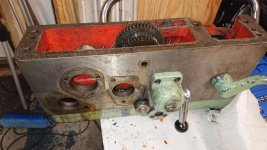
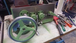
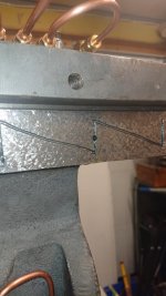
Pics show lathe, overview of bed as is now and the levelness along rear flat way (carriage way).

bed overview.jpg20180324 bed level along 1.jpg20180324 bed level along2.jpg20180324 bed level along3.jpgsvarven.jpg
 
Last edited:
Hmm, think I got the correct pics this time...

These pics should show Rear Flat Way (carriage) level / twist across.

Do note that I have not zeroed the level itself in any position so it is just relative the different measuring position, 4 over 1,2 meters / 60"


20180324 bed level across 1.jpg20180324 bed level across 2.jpg20180324 bed level across.jpg20180324 bed level across3.jpg
 
This post should now show carriage way level / twist across meaning rear flat way to front inverted V.

20180324  carriage ways across 1.jpg20180324  carriage ways across 2.jpg20180324  carriage ways across 3.jpg20180324  carriage ways across 4.jpg20180324  carriage ways across 5.jpg
 
Here´s some more pics on the crosslide in the midst.

The two rough ones are fromthe start after some two rough passes to break up the surface and then it´s the sides, one scraped perp to bottom and parallel to the sliding dovetail (LHS) and the right was too far out so milled it down. Had a good day in the mill and got it very nicely parallel on the first set-up and run so I´m leaving it as is for time being to just apply surfacing later.


crosslide RHS after milling.JPGcrosslide left side semi done.jpgcrosslide top 1 rough pass.jpg
crosslide bottom 2 rough passes.jpg
 
Thought I´d share some of the progress on the lathe.
Last I was working on the crosslide and there was quite an amount of material to be removed, both wear but also from not being “all square and flat” from beginning, surely the working surfaces should have been ok but the sides and top plane outside of compound area was.. loosely toleranced..
Anyway, that made for good scraping practice before finishing the sliding surfaces.

Pictures show various stages in fitting the sadel, aligning the crosslide, disassembly of the apron, clean and installing new bearings.
Compensation for wear and scraping of the bed was done by bringing up the apron again through milling of the underside of the sadel. This was a delicate operation since 0,25mm had to go. This was possible due to the fact that the idling transfer gear in the apron driving the crosslide leadscrew is offset significantly sideways so a change in vertical distance only affects actual C-C distance of the gears by a fraction. That and a most likely “healthy play” from start made this possible.
Special attention was paid to ensure correct contact pattern between apron and carriage was maintained as to not distort carriage ways when torqueing apron bolts.

Finally crosslide was fitted with the tapered gib and the accumulated sideways gap from wear and scraping amounted to approx. 0,5mm and was dealt with by epoxy-bedding a stainless steel shim glued in place. Gib was scraped flat for sliding on carriage side and mainly flat on static side towards the strip ensuring even contact pressure when adjusting the gib in future for wear.
Lubesystem has been installed and commissioned suscessfully. Front V-way is lubed on both sides on both ends so the V-way receives oil in four separate locations in individual Z-patterns.
Rear flat way has one Z-pattern on each side with individual feed.
Crosslide ways are feed from bottom and existing S-shaped oil-groove in crosslide bottom is positively connected at all times by means of the cross-cut groove in the opposing carriage surface.
System was bought from over-seas and I was a bit nervous if it would work out but so far I´m positively surprised. The distribution is even and well timed. Only negative would be volume is on the large side, however one can pull a bit cautiously on the lever.
Fitting the lubesystem as in layout and routing the parts and lines was the main challenge of it really. It also included drilling quite a few holes and plugging directing the oil where it needs to go. The oil line which is “in-the-air” will have get a cover on final installation when all is painted. The trade of in this position is of course Tail-Stock interference, however the Tail-Stock reach is rather adequate so I concluded this was the least trade-off compromise. Different lathe may be all different.

This is far from complete write up of the project, please feel free to ask questions or comment, all and any input is appreciated and being my first project I´ve had great help and advice from several along the way.

Next will no be to overhaul the feed gear box, mainly clean and replace all bearings and seal. Really most about getting to a flat gasket on the back side leaking oil slowly.
Then the Tail Stock and some paint! Oh yeah, the compound also…
 

Attachments

  • 37216425_201463383870712_6895250014369480704_o.jpg
    37216425_201463383870712_6895250014369480704_o.jpg
    100 KB · Views: 244
  • 37105317_199623737388010_8723401890429140992_o.jpg
    37105317_199623737388010_8723401890429140992_o.jpg
    96.2 KB · Views: 270
  • 37078687_199622490721468_122519169093599232_o.jpg
    37078687_199622490721468_122519169093599232_o.jpg
    98.8 KB · Views: 256
  • 37073097_199622394054811_252851064087248896_o.jpg
    37073097_199622394054811_252851064087248896_o.jpg
    99 KB · Views: 381
Mainly pics of lube system
 

Attachments

  • Screenshot_20180813-111938.jpg
    Screenshot_20180813-111938.jpg
    7.8 KB · Views: 182
  • thumbnail_DSC_1024.jpg
    thumbnail_DSC_1024.jpg
    98.3 KB · Views: 177
  • thumbnail_DSC_1025.jpg
    thumbnail_DSC_1025.jpg
    95.1 KB · Views: 158
  • thumbnail_DSC_1028.jpg
    thumbnail_DSC_1028.jpg
    94.3 KB · Views: 167
Mainly this an that...
 

Attachments

  • 37119439_199623177388066_4899673681682235392_o.jpg
    37119439_199623177388066_4899673681682235392_o.jpg
    101.1 KB · Views: 265
  • 37113061_199622987388085_2253133242116866048_o.jpg
    37113061_199622987388085_2253133242116866048_o.jpg
    99.3 KB · Views: 205
  • 37076026_199623107388073_7339264815761719296_o.jpg
    37076026_199623107388073_7339264815761719296_o.jpg
    99.7 KB · Views: 211
  • 39068269_223501951666855_935162659790127104_o.jpg
    39068269_223501951666855_935162659790127104_o.jpg
    99.1 KB · Views: 236
  • 36086859_842758075922039_8804106293016002560_o.jpg
    36086859_842758075922039_8804106293016002560_o.jpg
    96.5 KB · Views: 265
Beautiful! The scraping is wonderful! Makes me so proud to see students do so well and following up on what I ask them to do. "Pass it On" :-) It also shows the naysayers what I do is helping the industry. We also have to thank Practical Machinist for providing us this opportunity to share.

I would have done the lube a bit differently, but if your happy, that's all that counts for now. . I would have run the one tube under the saddle or inside the middle where the cross-feed nut travels. Other machines do that if there is room. If you leave it that way (pun not intended) then better make a TS stop so you don't hit the tube. Also you should make a cover for the other tubes as hot chips may erode the copper pipes someday.

Did you put in metering jets in the lube system or it a direct feed? They are also called metering units. That way they meter out small amounts of oil at a time as the pump slowly unloads the oil. Did you test the squareness of the cross-slide to the bed-ways? Also remember the headstock side (left) on the saddle should be higher .001" or 0.0254 mm then the tailstock side (right) because the left side wears faster then the right because dirt lays on the left side.


For the small use you give it plus you will be cleaning the ways I am sure you will never see the wear. It is a Rule of Thumb that you point or leave riding surfaces a bit high so as it wears it gets better, not worse. How are the way wipers? In my many years of doing and teaching I tell my students to epoxy grade linen Phenolic in the 1/2
's of the Tailstock by milling clearance so you install a minimum of .040" or 1.016 mm or put an insert under the tail-stock like Tyrone suggested. I never bore the TS to align it after scraping, I would bore or hone the TS bore and chrome plate or make a new (buy)a new quill. I have also Bored and Mogiced the Bore on a few Monarch EE's. Be sure to measure the side and top of TS so it points up and toward you to compensate for gravity and push away. minimum of .0002" - 0.005mm to max. .0005" - 0.0127mm. Be sure to add oil groves under the TS and make a felt pad to put in the recess of TS bottom 1/2 and a oil cup if it doesn't already have one. Thank You for attending the class and sharing what you learned and what you did yourself (thinking on your own) :-) Rich

PS: You may want to bolt on a flat weight on the front of the back of saddle to counterweight the pump if it is more then a few pounds. Better safe then sorry.
 
I see you've got the scraping bug. It reminds me of a shop I worked at. All sort of unusual surfaces were feathered or half mooned. Even the slides on the bench vices. Crazy. " Butterworth British Automatic Machine Tools " - they made a nice cam operated auto lathe. Long gone.

Regards Tyrone.
 
Thanks Richard for your prompt and attentive answer, I´ll try to fill in some of it.
It´s really a nice work to be doing and I think it´s coming on ok, for sure it will be lot´s better than from starting pont. Much thanks to getting started off in the right directions from class and for sure I´ve had lots of good advice along the way some from here and lots from our local Jan Sverre and others in our local “scraping community”, this is hard learnt on one’s own.
The Lube system yes, I am most happy with the fact that it is working! Haha The routing was cumbersome, I tried finding an interal routing along the cross-feed screw but no… And going under the bed felt un-safe in case it catches on the something out of sight. But yes, a TS - stop, I´ll add a rubber buffer!
The lube system has metering units one for each individual feed except for the front V-way where one metering unit feeds both sides of the V-way, however considering the areas lubricated this equates reasonably well.
Alignments
I´ve tested and measured back and forth, but yes squarness crosslide to bed ways and also against spindle in horizontal plane and against spindle square plane. Did some of these double and crosschecks to ensure I got same / similar results.

Wear provisions
As you mentioned I left 0,01mm on the sadle left side flat surface and also same 0,01mm on the crosslide.
Also I have been trying to ensure the sliding surfaces are “low-in-the-middle” to prevent any rocking. This goes also for the bed-ways of the sadel.

The way-vipers of the sadel are spring loaded ¼” thick felt vipers. I got new felt to install in them and make extra spares so they can be replaced.
On the TS there are no vipers from original but I plan to put something there at least.
Regarding the tail stock in general, the barrel and it´s locking mechanism seem ok however it has some wear underneath.
I have not decided yet which route to go yet but I can´t do anything (easily) in the middle / parting of it as the guiding section across is tapered in vertical direction meaning if I shim it there I´ll loose the guiding or I have to shim that too.
So right now it´s leaning towards Tyrones proposal(!) or just lift the headstock and scrape it straight down. I have not lifted it yet but from what I have seen it should sit on flats so really mainly just to scrape it straight down. Otoh, one should not fix what is not broken…
(I have contemplated electroless Ni/PTFE plating however I have not really found any previous references of this being used in this application and feels a bit like adding variables to a problem with known solutions, although the application under the TS appear to fit the specs of it. )

A few more pics
Sadle crossslide ways before, deep wear in the middle. Left this one flat, you can see the oil groove pattern from the crosslide used for final print. Alternated use of crosslide and SE during scrape in, after this I relieved centre part of crosslide slightly.
Indicatorpics shows left side being higher.
Lastly final blue up of underneath sadle to bed ways.

Sorry if I´m confusing with Sadle / carriage…
 

Attachments

  • 33553618_172850956731955_1166677086560059392_o.jpg
    33553618_172850956731955_1166677086560059392_o.jpg
    100.4 KB · Views: 179
  • 31946527_167968187220232_5714197899902976000_o.jpg
    31946527_167968187220232_5714197899902976000_o.jpg
    97.4 KB · Views: 197
  • 31942264_167968113886906_6483888139931746304_o.jpg
    31942264_167968113886906_6483888139931746304_o.jpg
    98.2 KB · Views: 190
  • 31749470_167314693952248_6094255943858520064_o.jpg
    31749470_167314693952248_6094255943858520064_o.jpg
    98.6 KB · Views: 176
Wear provision left - right side
 

Attachments

  • 33490027_172851276731923_5323787339791597568_o.jpg
    33490027_172851276731923_5323787339791597568_o.jpg
    100.5 KB · Views: 184
  • 33576494_172851270065257_7373170249669017600_o.jpg
    33576494_172851270065257_7373170249669017600_o.jpg
    98.8 KB · Views: 136
I see you've got the scraping bug. It reminds me of a shop I worked at. All sort of unusual surfaces were feathered or half mooned. Even the slides on the bench vices. Crazy. " Butterworth British Automatic Machine Tools " - they made a nice cam operated auto lathe. Long gone.

Regards Tyrone.

Ahh, it´s gotten me rather bad :) I´ve also noticed a secondary condition following presenting in a tendancy for hoarding stones, preferably vintage granite...
 
The scraping looks like Jig Bore specs. Also Jan was my first European student when he attended his first class in 2013 in Georgia and he is the person who invited me to Norway, Sweden and Denmark over the next 5 years.
 
I have not decided yet which route to go yet but I can´t do anything (easily) in the middle / parting of it as the guiding section across is tapered in vertical direction meaning if I shim it there I´ll loose the guiding or I have to shim that too.
So right now it´s leaning towards Tyrones proposal(!) or just lift the headstock and scrape it straight down. I have not lifted it yet but from what I have seen it should sit on flats so really mainly just to scrape it straight down.

I recently had to bring the headstock (HS) and tailstock (TS) of my cylindrical grinder into alignment. If possible you want to be scraping on the TS because it's so much lighter, hence easier to blue, lift, scrape, clean, lift, blue, lift,.... In comparison the HS is much heavier and so that slows down the process.

Have you checked the HS spindle alignment to the bed? If that is good, then it would make more sense to find a way to shim the TS. On the other hand if the HS spindle alignment to the bed is off, then you might as well mill/scrape the HS into spindle alignment with the bed. In this process make sure you end up with the HS a bit lower than the TS. Then you can scrape the TS down to match the HS.
 
Last edited:
If you look online for a PDF of the Testing Machine Tools book written by George Schleshinger. It has spec's on lathes and other machines. I used to have a link, but it stopped working. Scibd.com has a copy. They give it away fr 30 days. I have donated 2 times now, that's enough for now. Ballen is right on. Need to be positive the bed and saddle are square (out of square to cut concave) before testing the HS. Still a super nice job. Thanks. Rich

PS: Ballen will be attending one of the Austrian Classes. :-) I was thinking we should do another class in Scandinavia again sometime. I am hoping to be a tourist there someday too. :-)
 
Thanks for all the input and encouragement!

The Schleisinger book is in my storage, also printed out a desk-copy for studying.

At this point the measurements indicate all work so far is well within tolerances, including HS spindle alingment to bed (hor/vert) and crosslide travel (concave only) etc however before stating it as hard fact I want to confirm this by test-cutting (like two collar test) and also workload test to confirm it is stable and does not shift, unexpectedly, under various load.
So far these indications does support the route of not re-working the HS, indeed.

I´ll be disassembling the TS again shortly and I´ll put up some pics with initial findings and thoughts on it.

You won't find the " two collar test " in the Schlesinger book. Just saying.

Regards Tyrone.
 
Done!

Hi everyone,

Short update to this project. Just want to share that it has come to an end and the machine is ready for operation again. Actually I have already used it a few times, maybe 50-60 hours and it is such a total difference from before.
Parting which was a challenge (carbide 3mm / 1/8") is now just like sticking a knife in warm butter...

Thanks everyone who has contributed both actively but also to everyone who has gone before and shared knowledge and inspiration.


DSC_2166.jpg DSC_2163.jpg DSC_2162.jpg DSC_2158.jpg DSC_2157.jpg

On a side note I should mention at least parts of the "tail stock tale" as that´s pretty much where I left of last time.
The bottom part had wear to the bed of course, no worries there really. The top surface of the bottom part was however slanted alomost 1mm down towards front side of the lathe. And the tail stock barrel hole was worn, how ever the barrel itself was good.

Solution to this was:
Bottom part, I milled out one side of the female V-way hence lowering it to correct the slanting of the upper surface.
By allocating all milling to one surface I kept the other to "near net shape" having them as reference for alinging during scraping, although the scraping was really mostly some sideways step scraping.
Then I touched up the interface between bottom and top part. Bottom half was ground I think and to part scraped. Was not really any problem there, so really mainly just cleaning, stoning and pin pointing some high spots.
To fix the hole issue I bored it out to over-size and casted / injected a slideway epoxy against a steel core made to final dimension -0,01 and honed it carefully to a tight fit.
 
That was a lot of work and I am so glad you shared with us what you did. It sounds like you are really happy with the results and that makes all the effort feel so rewarding. I have to say the one thing I could never get over with the Stanko equipment I have been around is the gear noise. Boy those things were loud, I hope your lathe is a bit better than the ones I remember.

All geared machines are going to make noise but even a Stanko surface grinder made a heck of a racket. Of course that was the hydraulic pump shrieking like souls in torment. Ha Ha.

Charles


Back
Top