What's new
What's new

Tricky Diagnostic on a Sheldon Sebastian 13" Gear Head Lathe Cutting Issue

jahue

Plastic
Joined
Mar 14, 2017
I have been rebuilding a 1950s Sebastian 13" gear head lathe for sometime and I am 90% complete with the rehab. Just as a quick rundown, I rebuilt the apron (mostly cleaning and a few bronze bushings), I reconditioned the speed and feed gearbox (Couple of replacement gears, and a new phenolic gear), and I repainted the whole thing. Everything works great except I get a pattern almost like a spool of thread in all my cuts, independent of the lathe speed,tooling or the feed rate. I have isolated the problem to the spindle. I used a few other posts to trouble shoot and eliminate other possible issues. I have tried the following...

The lathe is level, with a calibrated machinist level.

New Belts, New Pulleys (solid steel, balanced, and trued) The Shaft on motor is running true.

I checked a wide range of feeds, speeds, and even hand feeding at a constant rate to eliminate the apron, and feed selectors.

Different cutting tools, all sharp

I went so far as to take the spindle out of gear, and turn just the spindle with a drill, using the feeding on the apron and feeding by hand.

And all of that I still have the pattern. I also have a slight vibration in the lathe at high speeds but I have triple check the feet and the leveling. I also have access to another machine that is almost an exact clone of mine and it doesn't suffer from the same problem with the vibration or the patterning.

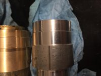
So I have tried my best with the help of everyone here to eliminate all possible issues other than the spindle bearings. So now I am to the spindle. Today I removed the spindle which came out like a dream mostly to clean it but also to get a look at the bearing cup and cone. At first glance they look really good. But in a certain light they have a wavy shimmer. You can't feel the pattern but you can see it. Both bearings cups show something similar. I cleaned every surface thoroughly and reassembled the spindle and checked the preload on the bearings and would you believe the pattern is still there.

Has anyone seen this before? I can get a Class 0 rear bearing, but the front bearing is almost impossible to find in a class 0... so much so I can't find one. Should I replace the back and see if that helps? Or am I likely to ruin a 650$ bearing.
IMG_6583.jpg
IMG_7153.jpg
IMG_7166.jpg
IMG_7143.jpg
 
I would assume but I have never replaced a set of precision bearings, I can get the back bearing in Class 3 or Class 0, the front bearing Is much harder to find in anything other than Class 2, I have found a Class 3 cup and cone but they are from separate online vendors both Timken Brand. So I am not sure if they should come as a set or not. I'm still not sure what is causing the patterning in the cut. I was hoping someone had run into something similar. I should add both bearings are single taper roller bearings.
 
It is free standing per manufactures instructions. According to the manual it only needs to be bolted if its on a wooden floor. The other Identical model is setup the exact same way.Leveled and resting on steel plates. I should add this pattern shows up at the very lowest speed, when the machine is completely free from vibration. It also shows up when running the spindle with a drill with the motor and gearbox uncoupled. I have in the past as part of my tests shimmed the base on all sides to ensue its not a vibration issue. The motor runs smooth as silk when uncoupled zero vibration. I have also positioned, balanced, and isolated the motor to ensure that is not the issue.
 
The wavy shimmer on the bearing race may only be the lapping from the factory; Does it look like a cross hatch pattern? These can still be visible for the life of the bearing unless the surface breaks down and starts coming off. This is one problem with the internet and diagnosing a condition, pictures are not the same as seeing in person. Another thing may be the work holding, maybe a different chuck or collet would act different? Lots of things go into cutting metal and the most minor detail may be the fix. One other question; is the cut on the part measuring round?
Dan
 
Fair enough jahue.

Looking at the photos the bearings are showing slight signs of wear but I wouldn't have thought they were at the point were they would be causing significant issues regarding work piece finish.

I have seen finishes like that before but I can't recall exactly what the problem was. It's a while ago now. I'll try and recall what the problem was. I do remember having a finish problem similar to that when the feed shaft was bent and causing the saddle to " pant " slightly.

As far as bearing replacement goes the convention was you shouldn't run an old bearing on the same spindle/shaft as a new bearing.

Regards Tyrone.
 
Does it make this pattern in just the Z axis or X as well? If only in Z, it almost seems to be due to the pinion gear pitch either too loose (or maybe too tight?). How does the hand wheel feel when traversing Z? Almost seems to be a 12 pitch insignia on the work piece. Maybe just a silly thought on my part.
 
It's much harder to tell if the X axis has a pattern, it does have a pattern but I'm unsure if its typical or related. I will try and take a picture. The one comment I can make is when I was testing this to isolate the carriage the pattern seems to swirl nicely but had more of a multiple tracks look than what I would assume is a constant spiral. And the hand wheel is smooth as silk for about 20+ inches near the head stock but near the far end of travel (Tail stock) its very stiff. This can be remedied by loosening the front carriage gib slightly. I attributed this to wear in the ways. I also flushed the apron and put in high quality way lub when I rebuilt the machine, and it is working great.
 
A partial update, I have access to another machine that is a model number A-6 the one i'm working on is an A-5 identical except for the length. It was suggested by Ken in another forum that it might be the carriage / leadscrew wobbling. His suggestion was to pull the leadscerw and swap it to the other machine that doest have this issue unfortunately it is to long. So I can't pull the leadscrew and swap them. But I have attempted to run some other diagnostics. The pattern shows up in all chucks new Bison 3 Jaw, Buck 6 Jaw, and 4 jaw. I haven't checked the 4 jaw this go around but I have in my previous tests. Yesterday I put a long bar in the machine and maxed out the distance I used a high precision live center. On the end closest (last 1inch) to the live center the pattern appears to go away, as the tool cuts the pattern appears about 1.5-2" from the far end and is present the remaining distance. I checked a few things late last night but they seem inconclusive thus far. I pulled the support block for the leadscrew and with my hand at the lower speed held the leadscrew to keep it from whipping and made a cut near the headstock mostly to see if the leadscrew was in a bind. The pattern was still visible. I also tried the threading lever... still there. I then pulled the leadscrew completely and hand feed the best I could at a constant speed... and it seems to go away, I won't say yet that its gone, its hard to be consistent when hand feeding the apron. I'm going to try and rig up a small motor to see if I can drive it without the leadscrew more consistently.

It's worth noting that I also quickly indicated the leadscrew near the gearbox and it runs out about .003, without the support on the other end, the other end runs out enough to see by eye. I did check the leadscrew with a very high end level (the straightest surface I could find) and it appears to be straight, even by eye it doesnt seem to be bent... I also did the roll test and it has no discernible wobble.

My bigger question is, can I detect with a .0001 indicator the wobble in the saddle if I measure off the ways? Or is there a way to isolate and narrow it down to either the spindle or the saddle?
 
How are you setting the pre-load on the bearings? Are the bearings getting hot after 20+ minutes? Is there any measurable runout at the spindle nose?

Does the pattern disappear if you use the tailstock?
 
It's two tapper roller bearings that face each other. and is set by a larger locking nut on the backside. The clearance is set by feel. According to the manual and many others, its set first by feel then checked for heat build up. If it get too hot then the locking nut is backed off 1/16-1/8 of a turn and tested again. It has to be hands down the worst way to preload bearings.
 
How are you setting the pre-load on the bearings? Are the bearings getting hot after 20+ minutes? Is there any measurable runout at the spindle nose?

Does the pattern disappear if you use the tailstock?

The headstock is warm but not hot, you could rest your hand on it all day. The spindle nose run out is .0002. And the pattern does disappear but only right at the tailstock for about 1".
 
I would suggest that you measure the thread pitch of that nut and do the math to figure out your pre-load. Snug up the bearing and then use the nut to set it for .0005 pre-load by turning the nut the calculated amount. Then check the temperature again.

The problem with tapered rollers is that they open right up as soon as the temp comes up. You might even be fine with .001 pre-load.
 
Another way to vary the preload in this design is to turn between centers, and vary the pressure through the tailstock. Because the pattern is present at all speeds, use a low speed, so heat does not become a factor. This also allows you to use a carbide dead center in the tailstock, eliminating a rolling bearing there.
Set the preload nut at the rear bearing set on the loose side.

With the above setup you can vary the preload on the headstock bearing, and see if that has any effect.

I wonder if the headstock bearings have been damaged by brinelling.
Brinelling - Wikipedia

I do not know if there is a way to test for this, or how easy it would be to see on a visual inspection.

You may need to change out the bearings using (relatively) inexpensive new bearings to see if that resolves the problem. If it does, then start the search for a better quality replacement.
 
Ok update I replaced the bronze bushings in the apron when I purchased the machine but I kept the old ones so tonight I put the old ones back in which are 1.04+ vs the new ones 1.00... to see if the leadscrew was lifting the carriage. no change. The bronze bushings also let the worm gear slop around more so if I had it too tight its now loose... but it still patterns. The gearbox is next, The one new gear I made was turned on the spindle thats in the gearbox so I know that gear isn't wobbling on top of the fact its phenolic. Not saying thats not it yet but I know it run true within about .0005. Im going to check the gears in the head stock and I may go through and replace all the non spindle bearings. I assume these don't need to be class 3.

I sent timken the pictures and they are not sure if the bearing wear pictured would produce that particular pattern. I did check the preload on the other machine... when I take it out of gear and give the chuck a flick it rotates maybe 2/3 of the way around, the one I'm working on goes around maybe 1.5 - 1.75. The other machine is noticeably stiff. Not saying its not worn out but its stiff. As a note the bed on that lathe drops .08 over about 20 inches. and the ways are beat. But it cuts like a dream.
 
What about wear on cross-slide and compound ways? Have you tried tightening the gibs, so that you feel a fair resistance to movement when the tool is more or less in position?
With a test or dial indicator mounted on a magnetic base, place it one after the other on all four wings of the saddle, with the point resting on the ways: move the saddle back and forth and try to rock it at different positions on the bed: do you observe any movement?

If you have a taper attachment, make sure that the clamp to the bed is completely loose or, even better, disconnect it completely from the taper attachment: it is surprising how much an unworn taper attachment could lift a worn saddle.

Make sure that the head is bolted down with equal tension on all the bolts.

Right now I would suggest not to mess with the spindle until you've ruled out these other factors.

Just my 2 cents.

Paolo
 
Can you measure variations in height of the stripes using a .0001 indicator?
We can see variations in reflected light that are caused by things small enough that they would not be measured easily in a shop setting. Does what you are seeing actually make a difference in the function of the parts?

If you measure the distance between stripes, does it change with the rate of feed, depth of cut, rpm, or diameter of the work?

After reading this thread several times, and reviewing the images in the first post after enlargement, I believe the bearings are the problem. Some of the rollers show grooves, indicating they at some point were run with contamination. Each roller makes multiple turns for each turn of the spindle. Bearings are designed so the number of turns of the rolls is not a multiple of the bearing turns. This prevents any variation in the roller or race from impacting the same spot every rotation and forging itself into a planetary gear pair. This design feature also means that any defect in the roller impacts the race and the bearing axis multiple tires each rotation, but not by an even number.

As an example easy to calculate, lets imagine a roller which makes one revolution every 5pi degrees (15.70796 degrees). When the roller have made 23 revolutions, the shaft will have turned 361.28315 degrees. If the roller defect is transmitted to the shaft, the mark will rotate around the shaft, and it will take 280.55956... shaft rotations before it occurs on the same location on the periphery. The mark from each roller would spiral around the shaft in a helix, just as a thread would. The pitch of the marks should be the same regardless of how the shaft is turned, the cutting tool, feed rate, or the diameter of the work.
 
Can you measure variations in height of the stripes using a .0001 indicator?
Yes its about .0005+ you can feel it when you run your hand down the part.


We can see variations in reflected light that are caused by things small enough that they would not be measured easily in a shop setting. Does what you are seeing actually make a difference in the function of the parts?

Yes, but I can remove it if I use the lowest federate, which probably just cuts so slow that its equalizing the hill and valley.

If you measure the distance between stripes, does it change with the rate of feed, depth of cut, rpm, or diameter of the work?

No, obviously at higher speeds it harder to detect but its the same in all feeds and speeds.

After reading this thread several times, and reviewing the images in the first post after enlargement, I believe the bearings are the problem. Some of the rollers show grooves, indicating they at some point were run with contamination. Each roller makes multiple turns for each turn of the spindle. Bearings are designed so the number of turns of the rolls is not a multiple of the bearing turns. This prevents any variation in the roller or race from impacting the same spot every rotation and forging itself into a planetary gear pair. This design feature also means that any defect in the roller impacts the race and the bearing axis multiple tires each rotation, but not by an even number.

As an example easy to calculate, lets imagine a roller which makes one revolution every 5pi degrees (15.70796 degrees). When the roller have made 23 revolutions, the shaft will have turned 361.28315 degrees. If the roller defect is transmitted to the shaft, the mark will rotate around the shaft, and it will take 280.55956... shaft rotations before it occurs on the same location on the periphery. The mark from each roller would spiral around the shaft in a helix, just as a thread would. The pitch of the marks should be the same regardless of how the shaft is turned, the cutting tool, feed rate, or the diameter of the work.

That makes complete sense. The one thing I wonder is that I might need to increase the preload to match the other machine. Currently it only rotates when out of gear .75 of one turn with a flick, the one I'm working on goes about 1.5 1.75 times.


I ran some further tests. I took the apron apart, took the saddle off, stoned and filed carefully all surfaces to make sure no burrs were standing. Blued the ways and put the saddle back on. Of course its not bearing 100% but its bearing all the way along the back side of the front way, either end and periodically on the back, mostly near the rear. I reassembled the whole thing cleaned every surface, new way oil, even surface lubricated, and readjusted all the gibs. I also filed the relief on the v grove to make sure it wasn't riding on anything it wasn't suppose to. Ran a test... same pattern, and this time I over tightened and under tightened (loose, very loose) the gibs front and back to see if the pattern changes. No changes. I moved on to the chucks, 3, 4, and 6 jaw all have identical patterns. I was even using the same rod to verify. The pattern also shows with the gearbox in neutral and hand feeding the carriage.

IMG_7260.jpg
IMG_7168.jpg


Back
Top