What's new
What's new

OT Opposed Piston Engine

manolis

Aluminum
Joined
Nov 25, 2006
Location
Athens Greece
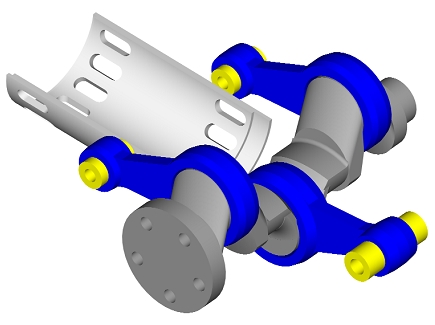
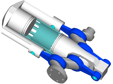
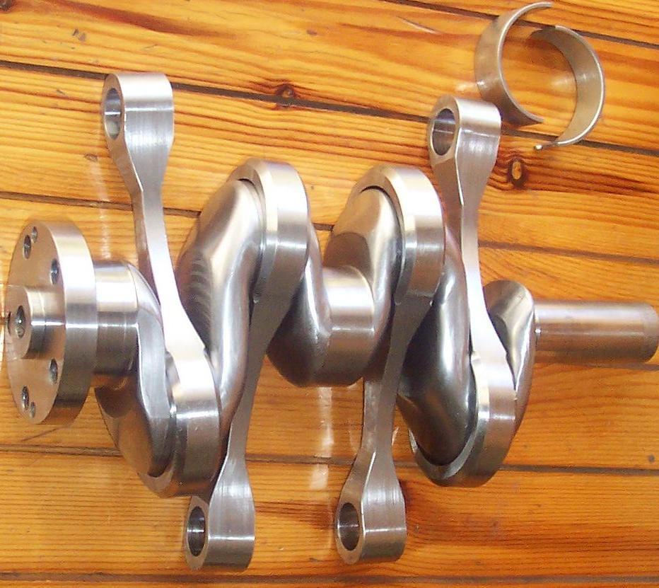
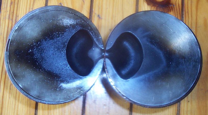
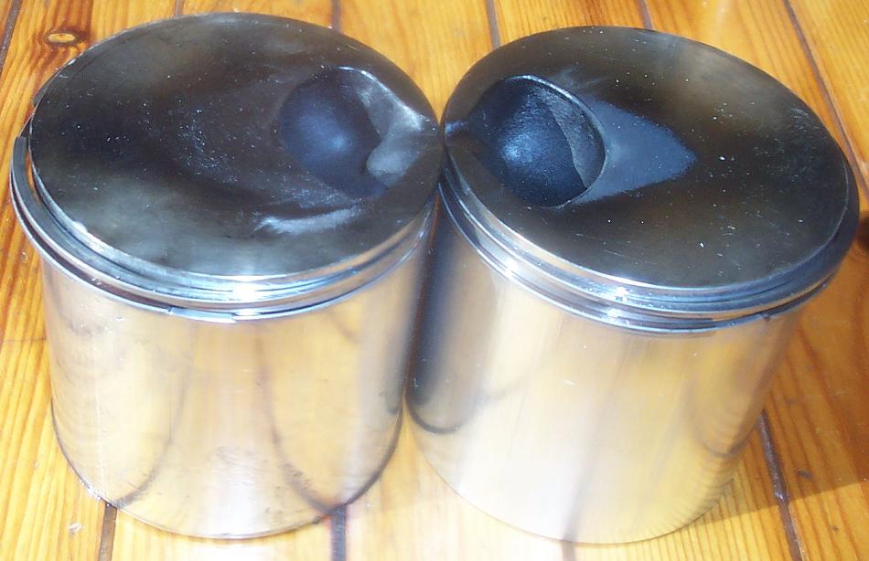
Here are the internal parts

PatOP1.gif


of the PatOP opposed piston engine, presented in details at http://www.pattakon.com/pattakonPatOP.htm.

Bore: 79.5mm
Stroke: 64+64=128mm
Displacement: 635cc
Compression ratio: 17
Scavenging pump bore: 130mm (1.34 scavenging ratio)
Total engine height: 500mm
Total engine weight (without the flywheel): less than 20Kp

It is an:
opposed-piston,
two-stroke,
single-cylinder,
single-crankshaft,
full-balanced (vibration free),
cross-head,
direct-injection Diesel engine,
with built-in "volumetric" (for a wider rev range and flat torque curve) scavenging pump,
with four-stroke-like lubrication,
and with some 35% as compared to the conventional, or some 20% as compared to the Junkers-Doxford and to the OPOC of EcoMotors, additional time for the injection and combustion of the fuel.

See the videos of this prototype running on Diesel fuel.

Question:

With your experience, what is your rough estimation about the manufacturing cost for such an engine in small quantities (say 1 to 10 pieces) and in medium quantities (say 100 pieces)?


The "angles" of the bevel gears:

OPREfly.bmp


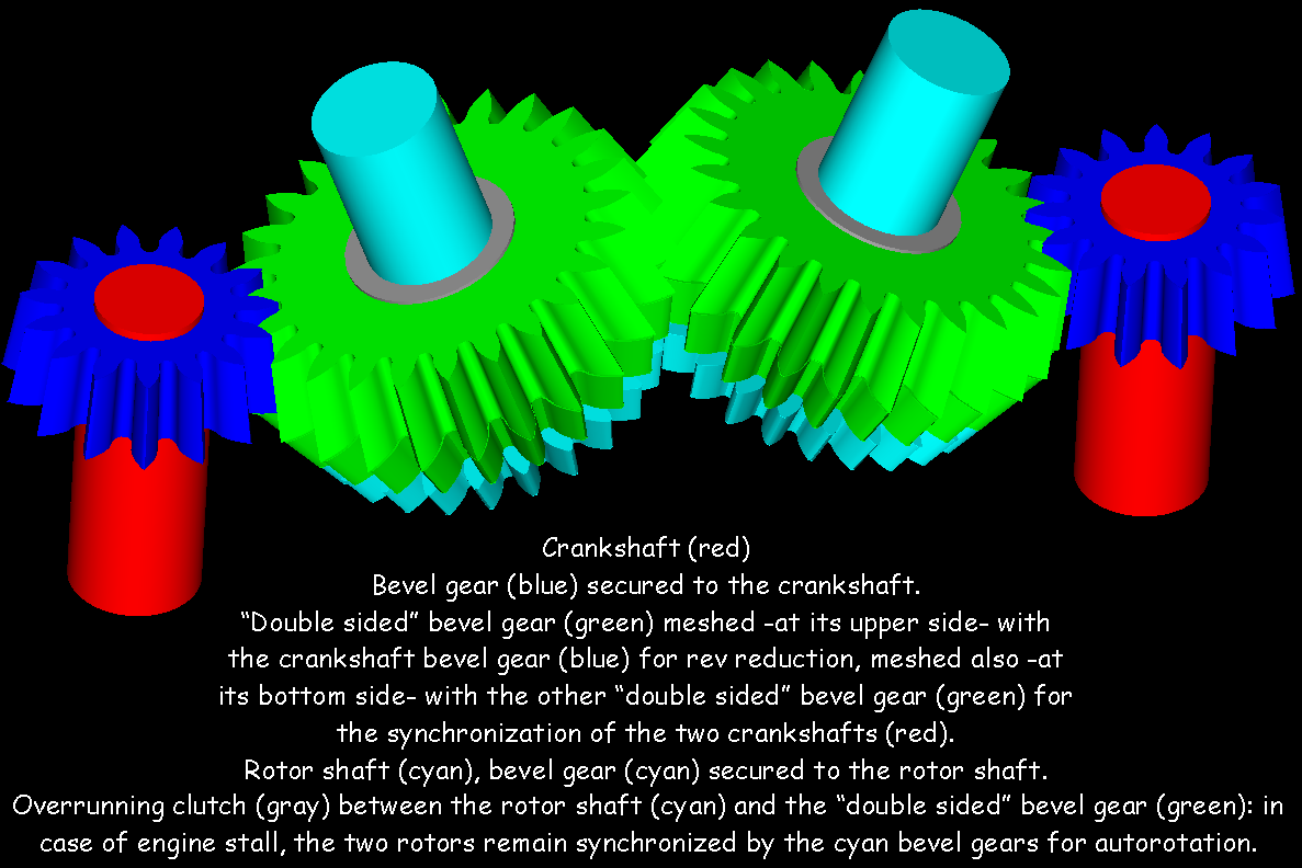
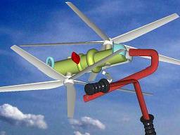
of a Portable Flyer (based on the OPRE engine at http://www.pattakon.com/pattakonOPRE.htm ) are quite small (say 5 degrees the smaller).

According the local "gear machinists", this machining is imposible.
Trying to make them in a "double head" EDM wire machine, the offered price (not to design, just to cut them) is unaffordable.

I know I can make "geometrically" correct bevel gears of this kind using a typical 4-axes CNC milling machine with a tapper end milling tool.
Any better idea?

Thanks
Manolis Pattakos
 
If it is a single crankshaft engine, why does your gear train have 2 crankshaft gears?

The real problem that I see is that a one cylinder engine has 4 connecting rods, four crankshaft throws. 2 pistons, and 4 bores to be machined, all of which cost money to machine.
If you did not have to add emission controls or any other regulatory crap, would this be competitive as a lawn mower engine? If not then all those problems will be greatly magnified when you try to produce a heavily regulated mover for a vehicle.
There is some brilliant thinking in this thing but you need to find a way to apply the KISS principle, in my opinion.

"If it is a single crankshaft engine, why does your gear train have 2 crankshaft gears?"

You are confused.
As I write, the gear train is for “a Portable Flyer (based on the OPRE engine at http://www.pattakon.com/pattakonOPRE.htm )”
The OPRE engine (Opposed piston Pulling Rod Engine)

OPREprotII.jpg


is different than the single crankshaft PatOP engine: the OPRE uses two crankshafts.
In case of divided load applications, the OPRE is better balanced than any existing piston engine in the meaning that its basis is rid of vibrations of any kind (like a turbine).
In comparison, the “perfectly” balanced Wankel rotary engine and the V12 engines of the luxury cars, are not as vibration free as the single cylinder OPRE.
This is so because the basis of the OPRE besides being rid of inertia vibrations of any kind, just like the Wankel rotary and the V-12, it is also rid of power pulses vibrations.
Imagine a Wankel rotary engine driving the propeller of a light airplane. After the ignition of the mixture, the power shaft (or crankshaft) of the Wankel receives a torque and, through the gearbox, passes it to the propeller. An equal and opposite torque is applied to the casing of the Wankel engine; the basis of the engine (i.e. the chassis /frame of the airplane) takes this reaction torque / vibration. The power vibrations cause the fatigue of the light frame; in a sudden change of the throttle position, the reaction torque may prove dangerous in the meaning that the light airplane may even flip upside down.
Now imagine the OPRE powering the same airplane, secured vertically at its nose. A first propeller is secured at the front end of the lower crankshaft, while a second propeller is secured at the back end of the upper crankshaft; a case like:

img6.jpg


or better shown at the windows / exe animation at http://www.pattakon.com/fly1/Flyer3.exe. The two propellers are counter-rotating. The power unit (i.e. the OPRE engine with the two propellers) applies to the chassis / frame neither inertia vibrations, nor power pulses vibrations, nor reaction torque; just a forwards force that moves the plane.
The reaction torque caused by the one piston/crankshaft on the OPRE casing is instantly and continuously counterbalanced by the reaction torque caused by the other piston/crankshaft on the OPRE casing.
Such a complete “ready to install” airplane power unit comprising a 500cc air-cooled OPRE direct injection Diesel engine and two propellers, will weight less than 20 Kp, and will combine better fuel economy than the current direct injection Diesels with perfect “vibration free” operation.


For the PatOP engine:
The connecting rods are single piece, lightweight ones, loaded heavily only in tension; each two of them share the relevant piston load.
The two crankshaft main bearings are constantly rid of load.
Each of the two pistons passes the trust loads away from the combustion cylinder, allowing “four stroke like” lubrication: at the height of the wrist pin there is plenty of oil, while a scrapper ring allows only a tiny quantity of oil to pass to the combustion chamber wall to lubricate the compression rings.
The additional time offered to the combustion (some 35% longer piston dwell at the Combustion Dead Center) allows more efficient combustion and cleaner exhaust as compared to the conventional di Diesels (if you need "less time" for the combustion of the PatOP, you can simply delay the injection; but if you need more time for the combustion of the conventional, there is nothing you can do).

The engine of Fiat 500 TwinAir is a two cylinder in line and uses one first order balance shaft (i.e. the balance shaft rotates with the crankshaft speed).
The balance webs on the crankshaft and on the balance shaft cancel the free inertia forces of first order (yet, the single balance shaft increases significantly the inertia torque on the engine frame; this is why engines like the two cylinder Yamaha TDM and the big singles use two first order balance shafts).
The twin of Fiat 500 has a heavy unbalanced inertia force of second order (just like the conventional four in line; the luxury four in-line use a pair of double-speed counter-rotating balance shafts to cancel this “vibration”).
The two-cylinder engine of Fiat 500 has one combustion per crank rotation (because it is a two-cylinder four-stroke engine).
For most testers-journalists the small twin engine behaves as a good four in-line (no particular rattle and noise).
It seems the two cylinders are adequate for small/medium cars and motorcycles.

In comparison, the single cylinder PatOP engine has, as a two stroke, one combustion per crankshaft rotation, just like the Fiat TwinAir.

The PatOP engine, without balance shafts and without balance webs on its crankshaft, is rid of unbalanced inertia forces of any order; i.e. it is better balanced than the Fiat TwinAir and than any four in-line.

Is the complexity / cost of the 2 additional bores, and of the two additional con-rods of the PatOP comparable to the cost / complexity of a cylinder head? Or to the cost of a balance shaft with its gear drive?

It seems the single cylinder PatOP engine is more than adequate for small/medium cars and motorcycles.

By the way: what makes the emission control of this Direct Injection Diesel more difficult than the emission control of any conventional Diesel?

Thanks
Manolis Pattakos
 
They have been around a long time.

... A very long time - almost as long as the internal combustion engine itself. The problems haven't gone away either.

The PatOP engine suffers from the same problems as any positive displacement scavenged diesel.

1. Scavenging efficiency decreases with speed.
2. Pumping losses are subtracted from crankshaft power.

Turbocharging, on the other hand, utilizes the waste energy of the exhaust gasses to improve scavenging. In some cases the amount of energy recovery is enough to add to the crankshaft output. This is done by gearing the turbochargers directly to the crankshaft.

The OPRE engine may resolve first order force couples but it does not eliminate the coefficient of fluctuation. That COF will still find its way to some elastic member of the system unless you employ sufficient flywheel inertia.

I spent years drawing sketches of what I thought were "revolutionary" engine designs. A graduate course in engine thermodynamics dispelled those illusions of novelty. It's all been done before.

They sure look impressive though!

Doug
 
See also the fairbanks morse two cycle opposed piston engine, here's some in
a submarine:

fwdeng1.jpg


2engine.jpg


engcrank.jpg


There's another crankshaft at the very bottom of the engine.
 
... A very long time - almost as long as the internal combustion engine itself. The problems haven't gone away either.
The PatOP engine suffers from the same problems as any positive displacement scavenged diesel.
1. Scavenging efficiency decreases with speed.
2. Pumping losses are subtracted from crankshaft power.
Turbocharging, on the other hand, utilizes the waste energy of the exhaust gasses to improve scavenging. In some cases the amount of energy recovery is enough to add to the crankshaft output. This is done by gearing the turbochargers directly to the crankshaft.
The OPRE engine may resolve first order force couples but it does not eliminate the coefficient of fluctuation. That COF will still find its way to some elastic member of the system unless you employ sufficient flywheel inertia.
I spent years drawing sketches of what I thought were "revolutionary" engine designs. A graduate course in engine thermodynamics dispelled those illusions of novelty. It's all been done before.
They sure look impressive though!
Doug

Doug:
“The PatOP engine suffers from the same problems as any positive displacement scavenged diesel.
1. Scavenging efficiency decreases with speed.
2. Pumping losses are subtracted from crankshaft power.”

The PatOP engine has a built-in “volumetric”, piston-type (the big diameter piston-crown at the bottom of the engine) scavenging pump of quite small dead volume.
This keeps a good scavenging (or better say a good breathing) efficiency in a wide rev range; wider than the conventional four stroke engines.
By the way, doesn’t the pumping losses of the (naturally aspirating) four stroke engine are subtracted from crankshaft power?

The PatOP prototype engine suctions some 850 cc (130 bore, 64 stroke) of air into the big bore cylinder and positively displaces it to the area surrounding the intake ports. If an obstacle (like a turbocharger, for instance) at the exhaust increases the backpressure just outside the exhaust ports, the scavenging piston continues to displace some 850 cc of air per crank rotation towards the intake ports area.

The PatOP engine takes the thrust loads away from the hot cylinder walls and away from the ports, enabling far lower lubricant consumption and better lubrication, just like the giant cross-head Sulzer engines; because the PatOP is a cross-head engine, yet a short one (for 79.5mm bore and 64+64=128mm stroke, the PatOP is only 500mm long).
In comparison, think of the inner-exhaust piston skirt of the OPOC engine (of EcoMotors) thrusting onto the hot cylinder, above the exhaust ports.

The cross-head architecture of the PatOP improves the scavenging efficiency too: because the combustion cylinder of the PatOP is rid of forces along the cylinder axis, and because the thrust loads are taken far away from the combustion cylinder, the ports area is significantly increased: the ports can cover almost all the area around the cylinder.

The turbocharging is always an option for the PatOP.
Yet the turbocharger restricts the efficient rev range of the engine because it adds its own limitations (peaky characteristics) to those of the reciprocating engine.

The old Junkers airplane engines were using centrifugal scavenging pumps geared to the crankshaft by a constant ratio of 10:1 or so; the engine had a sort rev range (defined by the characteristics of the centrifugal scavenging pump), providing a picky torque curve, making those engines good for cargo applications (wherein the engine operates constantly at its optimum revs / load), but not good for variable load / revs applications.


Doug:
“The OPRE engine may resolve first order force couples but it does not eliminate the coefficient of fluctuation. That COF will still find its way to some elastic member of the system unless you employ sufficient flywheel inertia.”

Yes, as in every even firing four-cycle engine having four cylinders (as well as two cylinders or one cylinder).
To make it easier understood: at zero crankshaft degrees the four pistons of the typical straight four engine (the most common engine on earth) have zero speed (the two are at TDC, while the other two are at BDC), i.e. the total kinetic energy of the pistons is zero. After 90 degrees of the crankshaft, the four pistons have high speeds, i.e. during the 90 degrees a good amount of kinetic energy was gathered by the four pistons. After another 90 degrees of the crankshaft, the four pistons have again zero kinetic energy. And so on. I.e. the flywheel gives – and takes back – kinetic energy to the four pistons: at 0 crank degrees the flywheel needs to have higher angular velocity than what it has 90 crank degrees later; in the first case the kinetic energy lost by the four pistons has been added to the flywheel (increasing a bit its angular velocity), in the second case the flywheel has lost a part of its kinetic energy which is absorbed by the four pistons.
The COF (coefficient of fluctuation) is used to describe the change of the flywheel angular velocity during a cycle.
The COF depends on the flywheel momentum of inertia, on the reciprocating mass (it is typically the mass of the piston, the mass of the piston pin and the mass of the upper one third of the connecting rod) and on the stroke of the reciprocating mass.

Compare the COF of the single cylinder OPRE driving a typical load (say the gearbox of a car) to the COF of a comparative conventional straight four.

Now imagine the OPRE driving the two counter-rotating electric generators of a range extender (or of a power generator set, in general). The fluctuation of the crank speed is an “internal affair” of the OPRE: the basis of the OPRE is perfectly rid of inertia vibrations of any kind, and of power pulses vibrations of any kind, too. Neither the Wankel rotary (even if FEV and AVL claim their Wankel range extenders have the best NVH properties), nor the V12 can achieve this.

You can also imagine the OPRE engine driving directly the two counter-rotating propellers of a small airplane, one per crankshaft (previous post). The propellers behave as lightweight flywheels of big momentum of inertia. The airplane frame feels nothing but a constant force ahead. Compare to the case a typical four in-line (or a boxer four) drives the propeller of the airplane.

You also can think of the additional time provided for the injection and the combustion of the fuel by the OPRE and the PatOP engines :

OPREdwell.gif


The table:

img18.gif


explains how much different are these engines, from the fuel viewpoint, than the typical ones. The animation below

droplet.gif


shows the upper 20% of the stroke of the piston of the OPRE / PatOP running at 6000 rpm and of the piston of a conventional (like the Fairbank-Morse or any other) running at 4500 rpm. If you cannot say which is the OPRE / PatOP and which is the conventional, neither the fuel droplets can.

Thanks
Manolis Pattakos
 
I would not call this off topic. The machine work is beautiful and the mechanics are artistry.
My only reservation would be cost of manufacture.
I see more possibilities , at least for starters as industrial applications where it should last almost forever.
 
How are you going to get the diesel to the center of the cylinder where it needs to be for decent combustion efficiency?
 
How are you going to get the diesel to the center of the cylinder where it needs to be for decent combustion efficiency?

You spray it in the pocket in the piston from where it can evaporate in a calculated way, just like in a prechamber in a normal Diesel engine. The evaporation also cools the piston.
 
You spray it in the pocket in the piston from where it can evaporate in a calculated way, just like in a prechamber in a normal Diesel engine. The evaporation also cools the piston.

I think prechambers disappeared with the start of emission regulations, even before high pressure common rail and piezo injectors. The other piston is where the injector needs to be.
 
I think prechambers disappeared with the start of emission regulations, even before high pressure common rail and piezo injectors. The other piston is where the injector needs to be.
Here are the pistons from above:

PatOP_pistons1.jpg


and here from the side:

PatOP_pistons2.jpg


The injector of the PatOP prototype has a single-orifice.
The poor quality of the injection system is compensated by the combustion chamber: the squeeze-generated swirl and turbulence into this smooth and compact and open (nothing to do with a prechamber) chamber combined with the long dwell of the pistons at the combustion dead center (CDC) improve the combustion efficiency and the clean exhaust of the direct injection Diesels.

PatOP_combustion_chamber.gif


As the two opposed pistons come close to each other at the CDC, their flat/smooth surfaces gather (concentrate) the hot / compressed air near the injector, into the chamber cavity, and keep it there until most of the combustion is completed.

In comparison to the four-stroke, the chamber of the PatOP is neither cooler than the intake poppet valves, nor hotter than the exhaust poppet valves, nor has valve pockets that destroy the geometrical and thermal uniformity (NOx and HC formation).

The reason the modern Diesels cannot do much after 4,000 rpm is that there is a long course of events in the course of time:
for the penetration of the spray,
for the evaporation of the liquid into vapor,
for the mixing with the air,
for chemical delay of ignition,
for propagation of the flame.
The modern Diesels cannot do much below 2000 rpm because of the turbo charger.
With a power band from 2,000 to 4,000 rpm, the driver of the modern Diesel needs almost twice as many gearshifts than a spark ignition (or a PatOP) engine.

Thanks
Manolis Pattakos
 
The PatOp looks a lovely conception to me.

As far as cost-effectiveness goes, yes, it has five pistons (counting the crossheads), four bores, and four con-rods, yet only one combustion chamber.

But that combustion chamber has the volume, therefore the fuel-burning, power-producing capacity of two. Since it is a two-stroke, it compares with a four-stroke four-cylinder engine, so in a sense it has only one "extra" piston.

And it has no valves nor valve gear, no heads (or very simple ones), no camshaft.

So I would guess its manufacturing cost, once tooled, would compare favorably with that of a conventional engine of similar power. It does not appear to have any weirdly shaped, hard to machine parts like the Wankel

I offer a couple of concerns:

Although the pistons see no side loads, I would not therefore short them on oil, since they need a good oil film to transfer heat to the cylinder walls. I'd use more piston rings.

Unless crankpin size is bigger relative to the rest of the crank than appears, or unless you use an assembled crank, I don't see how you can put the rods on without splitting the big ends.

Your crank is supported by only two bearings. It looks a bit slender, even just for the bending loads. Furthermore, since the torque from the pistons is coupled to the crank at widely separated locations, while the resistance is all at one end, I would check torsional stiffness or windup, lest the lag of one con-rod behind the other makes the pistons cock in the bore or the yokes break.
 
I offer a couple of concerns:
Although the pistons see no side loads, I would not therefore short them on oil, since they need a good oil film to transfer heat to the cylinder walls. I'd use more piston rings.
Unless crankpin size is bigger relative to the rest of the crank than appears, or unless you use an assembled crank, I don't see how you can put the rods on without splitting the big ends.
Your crank is supported by only two bearings. It looks a bit slender, even just for the bending loads. Furthermore, since the torque from the pistons is coupled to the crank at widely separated locations, while the resistance is all at one end, I would check torsional stiffness or windup, lest the lag of one con-rod behind the other makes the pistons cock in the bore or the yokes break.

magneticanomaly:
“Although the pistons see no side loads, I would not therefore short them on oil, since they need a good oil film to transfer heat to the cylinder walls. I'd use more piston rings.”

The small end of the connecting rod with the wrist pin and its bosses make difficult the cooling of the piston crown by the oil of the crankcase of the conventional engine; in the PatOP there is neither connecting rod nor wrist pin at the combustion side of the piston.
Besides, the skirts of the combustion-pistons of the PatOP recede “completely” into the crankcase area, once per crankshaft rotation at the BDC, wherein the air and the oil mist cools them down.

magneticanomaly:
“Unless crankpin size is bigger relative to the rest of the crank than appears, or unless you use an assembled crank, I don't see how you can put the rods on without splitting the big ends.”

The diameter of the hole of the big end of each connecting rod is 52mm. The crankpin diameter is 48mm. The plain bearings are from BMW 1600cc (2mm thick). The shape and size of the crankshaft arms (webs?) as well as of the crankpins allow the passage of the big end of the connecting rod; starting from the small end of the crankshaft, the first connecting rod passes one by one the intermediate crankpins and crankshaft arms to get to the first crankpin. The first half of the plain bearing is inserted by hand. The other half of the plain bearing is inserted / mounted by pressing it.
In a similar way the other three connecting rods are assembled.
The procedure takes some 5 minutes.

magneticanomaly:
“Your crank is supported by only two bearings. It looks a bit slender, even just for the bending loads. Furthermore, since the torque from the pistons is coupled to the crank at widely separated locations, while the resistance is all at one end, I would check torsional stiffness or windup, lest the lag of one con-rod behind the other makes the pistons cock in the bore or the yokes break.”

As compared to the version of the PatOP with the three crankpins:

patop4.jpg


(animation at http://www.pattakon.com/patop/PatOP4.exe ),

which is also the case for the OPOC engine of EcoMotors (wherein there are only three connecting rods per cylinder and only two main bearings at the ends of the crankshaft),

the four crankpins of the PatOP prototype, like:

patop5.jpg


halve the bending loads by spreading the forces along the crankshaft: the two external crankpins support the two internal and vice versa.

Thanks
Manolis Pattakos
 
Manolis,

I think I failed to make one of my concerns clear.

Unloaded, the pairs of crankpins are perfectly in line with each other. At TDC, they push the piston yokes to exactly the same heights. At 90 deg, they are still in line, and there is no difference in the distances from crank centerline of each piston's pair of rod-small-ends.

But when there is resistance to crank rotation at one end of the crank, the crank will twist, and the crankpins will be slightly out of line. At TDC and BDC, I think this will not matter, as the leading and lagging crankpins may be considered equally far ahead as behind the piston, so rod-small-end distance from crank axis will be the same, so piston yoke will still be parallel to crank and square to piston travel

But at 90 deg from TDC (and all other crank positions), a twisted crank will force conrods to different heights,and thus piston yoke will no longer be parallel to crank and square to piston travel. Piston may tend to bind or yoke to break.

I like your design and do not think this is nor intend it to seem a fatal flaw.. I only mean to suggest that you should design crank with sufficient torsional stiffness, and perhaps design some compliance into the connection between piston yoke and piston, so that pistons do not bind nor yokes crack.


I'll add a further suggestion. I believe you could dispense with the separate cylindrical cross-heads and their associated bores, by running the flat sides of the piston yokes between flat guides. The question here would be , is it cheaper to lengthen the yoke and machine those guides, than to bore and hone the cylindrical guides shown and provide separate cylindrical crossheads and piston rods. I think it would be, and also the guide surfaces could be smaller since a flat surface normal to the thrust can be smaller than the diam of a cylinder to carry same side load.

I am eager to see further development of your design
 
Last edited:
Manolis,
I think I failed to make one of my concerns clear.
Unloaded, the pairs of crankpins are perfectly in line with each other. At TDC, they push the piston yokes to exactly the same heights. At 90 deg, they are still in line, and there is no difference in the distances from crank centerline of each piston's pair of rod-small-ends.
But when there is resistance to crank rotation at one end of the crank, the crank will twist, and the crankpins will be slightly out of line. At TDC and BDC, I think this will not matter, as the leading and lagging crankpins may be considered equally far ahead as behind the piston, so rod-small-end distance from crank axis will be the same, so piston yoke will still be parallel to crank and square to piston travel
But at 90 deg from TDC (and all other crank positions), a twisted crank will force conrods to different heights,and thus piston yoke will no longer be parallel to crank and square to piston travel. Piston may tend to bind or yoke to break.
I like your design and do not think this is nor intend it to seem a fatal flaw.. I only mean to suggest that you should design crank with sufficient torsional stiffness, and perhaps design some compliance into the connection between piston yoke and piston, so that pistons do not bind nor yokes crack.
I'll add a further suggestion. I believe you could dispense with the separate cylindrical cross-heads and their associated bores, by running the flat sides of the piston yokes between flat guides. The question here would be , is it cheaper to lengthen the yoke and machine those guides, than to bore and hone the cylindrical guides shown and provide separate cylindrical crossheads and piston rods. I think it would be, and also the guide surfaces could be smaller since a flat surface normal to the thrust can be smaller than the diam of a cylinder to carry same side load.
I am eager to see further development of your design

Magnetoanomaly,
thank you for your strictly technical comments.

In the PatOP engine the clearance of the combustion pistons can increase without side effects (no thrust loads, no need of cooling by the cylinder wall).
Also the support of the combustion pistons (the exhaust on the horizontal “bar”, the intake on the member between it and the scavenging piston) can be modified, if necessary, to take any “twisting” of the crank
Also the twisting stiffness of the crankshaft can increase as desirable, by increasing the crankpins diameter and the size of the webs.
Yet the practice (operation under full load) "says" that the stiffness of the existing crankshaft is adequate.

And talking about the twisting stiffness of this short crankshaft (the crankpin diameter is 48mm, the center to center distance between the fist and the forth crankpins is 133mm, the eccentricity of the cranks – i.e. the crank arms - is 32mm):

PatOPpro6.jpg


if the twisting of the crank at middle-stroke causes an angle offset df between the 1st and the 4th crankpins (which, in turn, causes an offset ds=df*32mm between the two side pistons along the cylinder axis), at a first approach the angle offset df1 of the exhaust combustion piston about the cylinder axis is some four times smaller: df1=df0*(32mm/133mm).
By the way, compare the twisting stiffness of this short crankshaft to the twisting stiffness of an in-line six BMW crankshaft (more than 500mm long) and of the boxer six cylinder Porsche crankshaft (these engines have no yokes to crack by the angular offset between the first and the last crankpins, yet any significant angular offset – i.e. oscillation - between their crankpins is quite risky).

The cylindrical form of the side pistons makes the manufacturing (of the prototype at least) easier. The Sulzer-like flat cross-head is an option.

For everybody in this forum:

Neither the 1st question set:

With your experience, what is your rough estimation about the manufacturing cost for such an engine in small quantities (say 1 to 10 pieces) and in medium quantities (say 100 pieces)?

nor the 2nd question regarding the manufacturing of the small angle bevel gears,
were answered, yet.

Thanks
Manolis Pattakos


Back
Top