What's new
What's new

Qt10n spindle want turn on

dipiazzamachine

Plastic
Joined
Feb 12, 2010
Location
Pa USA
My lathe was running fine, came in this morning, and when I tried to start the spindle I get a red alarm, 20 nmi emergency stop. I reset and restarted , Everything works except the spindle. I can move axis around , change tools, move tailstock, but as soon as I try to turn on the spindle it errors 20 nmi emergency stop. I have played with the e stop button and it seems to be working fine, I have tried to start in auto mode and I get the same error message. any Ideas on what the problem is?

Thanks for any input or advice..
 
Go to diagnostic screen before trying to clear the alarm. You should have more than one alarm showing. Just guessing but it sounds like the spindle VFD is drawing more current vs what you can provide.

You can slow down the spindle acceleration 'parameters' (which will reduce the AMP draw when spindle starts) by changing some of the settings on the #5 DIP switch located on the FR-SE drive. Take a picture of the switch for us, but do not go adjusting it blind.

Your answers to these questions may provide more insight into the reason behind the spindle alarm:

How are you powering the machine? RPC or utility 3 phase?

Did you verify the internal transformer is set correctly for your incoming voltage?

Is the machine phased correctly?
 
X2 on exploring the diagnostic screen before clearing, or cycling power to clear.

Also look at the spindle amp for alarms.

FR-SE's have a row of LED's on the left side and a decode chart on the front cover.
FR-SF's have a digital display, along with a chart on the front of the drive.

Frequently an IOC fault is the reason. Beyond finding the bad transistor, you should verify the (close to 20) output voltages of the power supply at the top of the amp are all working, and check that the fans on the top of the heat sink are still running.
Mitsubishi will fax or email the procedures for the above checks if you ask for them, they are at 1-847-478-2500 and pick the option for tech support, it's free.

If running on an RPC over voltage and under voltage alarm may be seen.

Measure the actual voltage at the bottom of the circuit breaker in the amp. Measuring phase to phase only, and not to ground.

Bill
 
Where is the diagnostic page at?

I am using utility 3 phase power.

My spindle drive is a FR-SE. the 1st and second red led is lit up after the error.

thanks for the responses.
 
Where is the diagnostic page at?

Really? :skep:

Push left soft key on monitor, the same set of soft keys that display position, tool set and parameter soft keys, also displays the diagnostic soft key (last one on far right of screen).

Still need to know if machine transformer is strapped to your exact incoming voltage. Transformer is adjustable in 10v increments and makes a HUGE difference in how long the machine will live before throwing alarms and burning out expensive components--namely the FR-SE drive.

Still need to know if machine is phased correctly. Backwards phasing will cause axis drives to overheat and fail in a matter of weeks. Reversing the leads on the hydraulic pump to get it to spin the correct way does not correct the backwards phasing in the machine. Use the VFD indicator LED to verify phase is correct.

Here is what the FR-SE spindle drive LEDs look like (viewed through sheetmetal cover) when machine and control are powered up and spindle at rest (1st pic) and spindle running (2nd pic).
 

Attachments

  • FR-SE Spindle Stop.JPG
    FR-SE Spindle Stop.JPG
    65 KB · Views: 267
  • FR-SE Spindle Running CW.JPG
    FR-SE Spindle Running CW.JPG
    63.6 KB · Views: 182
Probably, more than likely, almost certainly, I would bet on it, that you have a bad spindle drive.

If you can't diagnose and repair yourself, yank it out of the machine and ship it to MEAU in Chicago.

Warning: the FR-SE is heavy, probably 75 pounds or more.

Good luck,

Greg
 
If the top 2 LED's are lit, please verify that there are 2 below the lit ones that are not lit. It is very common to give a quick look and actually be looking down so the middle 2 lit LED's appear to be the top two.

The top 2 lit is IOC fault
The middle 2 lit is external emergency stop.

With the data we have, it could be either one, both will give the 20 nmi emergency stop. The troubleshooting method is not the same for both alarms.

I have been called a couple of times to fix the IOC fault and is really an external emergency stop problem .

If it is an IOC alarm, It is wise to explore several things first so you won't damage it again, after the repair.

1. Insuring that the transformer is set to the correct taps as Philabuster advises in posts #2 and 5 and my advice of measuring the voltage at the input to the FR-SE in post #3, this also makes sure all phases are there and at the proper voltage.
Post measurements. We can guide you thru the tests.
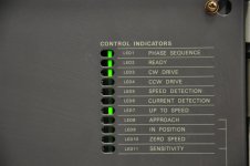
2. Insuring that the phase rotation LED is lit as pictured in post #5. It may or may not run if this LED is out, depending on the drive parameters. It should always be lit.

These conditions can cause early failures of the FR-SE.

Other conditions that should be checked is the power supply outputs before removing the unit for repair. A single one missing, even intermittently, can, over time cause a transistor failure that gives an IOC fault.

If one or more is observed as missing, the power supply needs to be repaired or replaced as part of any repair that replaces the failed transistor. This can save future repairs that seem to just make it past the warranty period.

If it is an external emergency stop fault, there is a lot of checking needed to determine what is causing it.


Where in PA are you? I will be near Brookville mid next week.

Bill
 
I am near Pittsburgh Pa, I have contacted Mitsubishi thru a repair man, they quoted $4500.00 to repair and warranty for 1 year, I have also contacted ICS, they where about $1500.00 less. Which one would you send yours to?

Have any of you guys ever fixed one of these yourself? what is involved?
 
I am away from my notes right now but I believe the FR-SE I worked on had an IOC fault. It turned out to be one of the current sensors sitting on the capacitor bank deep inside the drive. I recall that MEAU had the part for $100 or so. Figuring out the problem with the info MEAU could release plus what I could find on the 'net probably cost more than $4500 even at say $50/hour.

I also found that some of the low voltage electrolytic capacitors on the driver board were bad and needed replacing. MEAU also made a design error and didn't provide enough pins in the connector between the control and driver boards and some contacts burnt after a while.

I was fortunate that none of the power semiconductors or modules were bad as they are hard to get.

There are a couple of downloadable documents on MEAU's website and I would start there checking for bad parts and if OK then checking the adjustment of the IOC. I might be able to answer some questions if you want to continue with the repair.

Best o' luck,

Duane
 
which transistors are the ones you guys are referring to? are they the ones on the second board in, 12 of them with heat sinks around them? can I test them while soldered on the board?
 
The MEAU document needed is BNP-A7237-35A and is downloadable at Mitsubishi Electric Automation Inc. - MEAU Home. The search on MEAU's home page seems to find it right away.

The troubleshooting section starts on page 90 of the 2nd section (as indicated by the number at the bottom). Page 93 shows the IOC fault and how to test for causes.

An electrical meter is needed for some tests and adjustments. If the meter has a diode check function, a simple in circuit test can be made on the transistors on the driver board or the main chassis. I can't remember exactly what type they are but if the number is readable I can probably explain how.

I would also check to see that 5.0 volts is present between the two screw terminals on the upper left corner of the front board. If significantly different (ie. < 4.80 V) then the pin/contact on one of the inter-board connectors may be faulty. The MEAU tech said this was not unknown but it wasn't documented.

Cheers,
 
I am not the least bit familiar with the error codes etc. that you all are talking about......not that you are wrong....I just dont work on machines......I operate and program them.......however from the get-go.....did you make sure the spindle was clamped?...O.D vs. I.D. clamp set correctly?.....everything homed?......chuck not at the bottom of its stroke?.....ALL estops released (Estops on the back of machines are smart-ass magnets). Lube (S) are all topped off?...You seem to be beyond this point....but I worked on a motorcycle I had for 3 hours once before realizing...it was out of gas...lol
 
Go to diagnostic screen before trying to clear the alarm. You should have more than one alarm showing. Just guessing but it sounds like the spindle VFD is drawing more current vs what you can provide.

You can slow down the spindle acceleration 'parameters' (which will reduce the AMP draw when spindle starts) by changing some of the settings on the #5 DIP switch located on the FR-SE drive. Take a picture of the switch for us, but do not go adjusting it blind.

Your answers to these questions may provide more insight into the reason behind the spindle alarm:

How are you powering the machine? RPC or utility 3 phase?

Did you verify the internal transformer is set correctly for your incoming voltage?

Is the machine phased correctly?

HI, im having trouble with my Mazak Slant turn 15 Mazatrol T-1 control, everything Works the spindle jogs, but when i try to spindle start it shows an alarm 130 spindle run inhibit alarm. what could it be, it has been a couple of years with this issue, cant get it to work. any ideas?


Back
Top