Piece-o-cake. I do this all the time.
")
Define as normal OD groove tool. Be sure to enter the exact width and radius of the grooving insert. For example say you are using .062" wide tool with .007" corner radius.
The old controls are not designed to use a groove tool as a turning tool, but it can be made to work.
Program the job as you would BAR OUT (not grooving cycle), but you need to adjust the geometry on the trailing Z side of the insert to account for the flat on the groove insert between the corner radii. In this case, .062 -.007 -.007 = .048".
The machine will automatically compensate for a full radius tool, but ignores the flat on this insert. Solution is to manually add .048" to the Z lengths
on the trailing Z side of the geometry (only 3 dims, start of CHF, start and end of .484 rad.) and run the program with rough and finish tools. Lead side of geometry is unchanged.
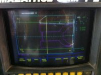
The geo on the screen will look wrong, but when you run a simulation or trace, you will see the tool cut the geometry correctly.
The above is not necessary for turning ops with full radius groove inserts as they work fine.
This takes a few seconds to change the geo. Program the job manually? F that.

You could even rough the profile with the VNMG with correct geometry without a finish tool. Then on a second process, use the above method with CPY OUT rough and finish tools (or just a finish tool) to remove the uncut portion left from the previous VNMG tool. (process copy, adjust Z values and change tool info, done)
 Hi Guys,


 Often times, they end up doing this number trying to leave:
 so I settled for an avatar of my 8" chuck sporting ridiculously oversized 15" jaws instead.