What's new
What's new

Cone angle and CMM

methodman

Plastic
Joined
Oct 24, 2016
Hello all,

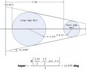
I am in need of some assistance. I have a customer who needs to identify a cone angle on the part shown below at (89.8°) and they have specified that a 2 ball gage should be used to acquire through cmm machine. I am not familiar how the idea of using this method is done through cmm and how to acquire the angle or how to start by going about this. Find diameter of the 2 balls? Have them specially made to sink into the cone and have the cmm probe to acquire the angle?

Cone angle dimensions.jpg

Example I found:

Cone angle example.jpg
 

Attachments

  • Cone angle dimensions.jpg
    Cone angle dimensions.jpg
    57.6 KB · Views: 877
The 2 ball method is normally (at least in my 35 years of inexperience) used to define longer tapers than what appears to be a countersink on your part. The note for 80% contact on a gauge would seem to overdefine the surface with the 2 GS&T callouts at the different depths. just one opinion. AND, unless that surface is ground, even if you blue up the gage, a machined taper is not going to give you great contact anyway.
 
While I think the engineer needs a good shake. No space for two balls at once but one ball slightly larger than the bottom Dia. and another slightly smaller than large top Dia. and measure the relative height difference and do the math. However the CMM should be accurate enough in the first place. Your buyer may not have CMM and he is looking for you to supply a checking method for free. I suspect they are whistling in the wind, especially without a grind or lap to obtain the wring %. LOL.
 
I have used ball over on short tapers. On a height gauge or dial indicator. I would not like to measure something not on or as per a print. It also seems like the angle is double tolerance. As to angle and location. Plus a profile of a surface for basically a flatness or form of the surface. I would say they are going backwards in requesting Ball over. Still, it a quick and dirty method. I think its more of a CAD and calculation to achieve what they want.

Edit: I finished a CMM WO with a Ball measurement. Not Ball Over Ball though. I had to look at the print again. The measurements are coming from datum F. Look at D1 and D2. You will need to find Gauge Balls that will fit closely to the angle at these points. Measure a sphere to the larger top Gauge Ball. Set its top with a point and a plane parallel to F. Then remove and insert, measure smaller bottom ball. Might be close on your probe size. Record actuals. Probably include measuring as per the print. My best guess, is your customer is wanting to see what size Gauge Balls and tolerances to them would work. Then they can be measured at the production line, with a height gauge by operators.
 
Last edited:


Back
Top