What's new
What's new

FaroArm Reverse Engineering

John_Boy

Plastic
Joined
Jul 17, 2014
Location
VA
Morning!

Company recently purchased a 9ft FaroEdge Arm, and I am somewhat familiar with Cam2 Measure10 program it came with. Getting to the point; I've been asked to reverse engineer some extrusions we recieved from sub-contracting (I will attach dwg). Basically i need to do something like this (https://www.youtube.com/watch?v=RSfZFBsx_a8) just with CAM2 Measure10 software. Would i be able to take multiple points, contruct my lines/arcs/etc. , then extrude like the video?, or will i have to just measure Lines,circles, etc.? Some of the radius' are pretty difficult to get using a 6mm probe. Any feedback would help!

Thanks in advance,

John_Boy

What i'm working with!
-9ft FaroEdge Arm
-6mm Probe
-CAM2 Measure10
-Autodesk Inventor 2015

s/n: Extrusion 12ft longext.jpg
 
There is no law that says you have to measure every attribute or feature with the FARO. Measure as much as you can, then apply radius gages, depth mikes, etc. as needed. (Or that's what I would do.)
 
There is no law that says you have to measure every attribute or feature with the FARO. Measure as much as you can, then apply radius gages, depth mikes, etc. as needed. (Or that's what I would do.)

I agree with Bryan to measure as much as possible with hand tools. You're going to struggle with a 6mm probe. A 9ft long faroarm isn't really the ideal tool for your application. You'd probably be better served with a cross-section and an optical comparator.

I'm not familiar with the software you're using, but I assume you'll want to export your geometry from the faro software to your autodesk software. Again that's the typical way it works based on how most inspection/cad software works that I've used. The guy in the youtube video was using some type of rapid prototyping software which is different all together. If you get stuck once you have collected the data, post here and I or someone else can help talk you through the logic of making your solid model.
 
My solution:

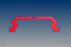
Traced profile using the Polyline feature in CAM2 Measure 10, exported the points into an .iges file, imported it into Autodesk Inventor 2015, projected the radius corners onto a new plane, then connected the tangent lines all together!

With the data, i was able to compare the face of the extrusion we recieved to the dwg @ max tolerance.

Thank you helterskelter & Brian Machine for your help!!!MIN-MAX-NOM.jpg
 
Looks like you got it to work great and that's the main point. I thought I would comment because I use a FARO arm with CAM2 Measure 10 as well a DezignWorks (and a few others) on a daily basis. Sometimes it is difficult to accurately achieve a repeatable measurement on a radius with a portable CMM. In circumstances like you encountered, I would probably measure the part exactly the same as you did but once I transferred into my CAD software I would simply extend the individual lines into sharp corners and then use the fillet tool to create the proper radius. As mentioned, I would use a radius gauge to verify each radius. The DezignWorks software that you linked to in the YouTube video is pretty cool, it allows you to use the FARO arm to measure a part and actually create sketch geometry within Inventor. In essence, you can measure a few items while creating their associated sketch entities, create a extrusion, revolve, etc. and then measure a few more items, create additional features, etc. The nice part about DezignWorks is that if you forget to measure something on your part, it's very easy to create another sketch and measure that entity, all inside of Inventor. No exporting, importing, etc.


Back
Top