What's new
What's new

How to make a FAB

Take a chunk of square bar. Drill and tap a through hole for the upper and lower posts. Drill a through hole where the adjusting screw will go. Cross drill for the hinge. Hacksaw the slot from the end to the hole you cross drilled for the hinge. Tap one side of the second through hole, and redrill the other side for clearance on the adjusting screw. Thread your upper and lower posts, perhaps with a small shoulder, to fit the first tapped through hole. Assemble.

Spend as much, or as little, time as you want rounding over ends of things, cleaning up saw-cut surfaces, etc. Files are your friend, although a 6x48 belt sander will make trivially quick work of rounding over.
 
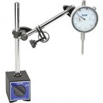
A friend gave me a beautiful old Mitutoyo Magnetic Base that he got from a garage sale. It needs a Fine Adjustment on Base to really be useful. It is similar to this: Brown & Sharpe 599-7765 Miti-Mite Heavy-Duty Magnetic Base Any suggestions on how to do this with a lathe and hand tools.

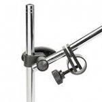
From what I see from the picture it already has a fine adjustment screw. It's only a question of rotating the cylinder (90º) so the adjustment screw can be utilized.

Brown-Sharpe-599-7765-Miti-Mite-Heavy-Duty-Magnetic-Base.jpg

Maybe this makes it easier to see what I mean.

HG1.jpg HG2.jpg
 
Dear Gordon, Thank you. Yes, I did. It tells that the FAB is only useful when it is oriented in a position such that it moves the indicator towards or away from the feature it is indicating on. The base I received had a broken FAB which has now been lost. So, I need to make a FAB to be able to connect the post to the base and to provide some fine adjustment. I'm sorry that my first post was not clear. The photo I provided was of a similar base to mine so as to show what I need.
 
Dear Gordon, Thank you. Yes, I did. It tells that the FAB is only useful when it is oriented in a position such that it moves the indicator towards or away from the feature it is indicating on. The base I received had a broken FAB which has now been lost. So, I need to make a FAB to be able to connect the post to the base and to provide some fine adjustment. I'm sorry that my first post was not clear. The photo I provided was of a similar base to mine so as to show what I need.

My wife and I were on vacation in Thailand less than a month ago. Chiang Rai, Chiang Mai and Hua Hin. 15th time in Thailand so we must like it.
 
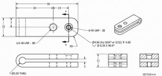
@sfriedberg, here is my drawing with my best guess at what the dimensions should be. Perhaps you or someone could comment on dimensions. Perhaps 15mm is too wide. I wonder about the spacing between the holes as well.FAB-1.jpg
 
@sfriedberg, here is my drawing with my best guess at what the dimensions should be. Perhaps you or someone could comment on dimensions. Perhaps 15mm is too wide. I wonder about the spacing between the holes as well.View attachment 223854

Why would you want to give yourself a 3B tolerance on the threads? 2B is standard.

http://f-m-s.dk/3.04.5.pdf

Half of 15 is 7.5. Have a feeling others will find more.
 
I wouldn't countersink the clearance hole for the adjusting screw. You want to use something like a thumbscrew, with the head bearing on the top surface. If you're fancy, you can groove the thumbscrew 4mm (per your drawing) below the head and fit a retaining ring to "capture" the top leaf. That would give you more positive motion when loosening the adjusting screw.

And Gordon caught a classic CAD trap. Setting the printable number of decimal places is not the same as setting a printable number of significant digits.
 
Thanks @sfriedberg and Gordon,

Because I set the tolerance key by the number of decimal places (precision), the rounding of the numbers doesn't come out even. I'll have another think on that.

I do have the original thumb screw which has a fillet on it - so I put in the counter sink to accommodate the fillet. I didn't realize I had inch threads until after I had drawn everything. I was expecting metric from Mitutoyo. I want to go back and check the clearance hole size.

That's an interesting idea to "capture" the top leaf. OK 2B thread class it is Gordon.

Thanks for your comments.

What I'm really looking for is feedback on the size of the piece; the width, length and hole locations.
 
I've redesigned it a little. I'll try the M3 x .60 because I have the tooling.
FAB-2.jpg
Here's the work in progress: 2018-03-23 16.30.08.jpg2018-03-23 14.46.06.jpg
My son Peter is working on it. He attends a technical high school here in Thailand and enjoys precision filing.
 
I've redesigned it a little. I'll try the M3 x .60 because I have the tooling.
View attachment 224001
Here's the work in progress: View attachment 224003View attachment 224004
My son Peter is working on it. He attends a technical high school here in Thailand and enjoys precision filing.

I don't know whether to laugh or cry. Find standard screws first and then make the necessary threads.

You're making a single, simple clamp, not mass producing space vehicles.
 
Last edited:
Let me clarify my situation:
I have the original #6-40 adjustment thumb screw from the broken FAB. I do not have a tap this size nor is it easily available from a village of 250 families in rural Thailand. I'd have to get it from the states.
In the provincial capital 32 km south, there is a fastener store that has M3 X .50 screws. I don't have a tap that pitch.
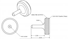
I do have an M3 x .60 tap and a die. It seems the most expeditious way for me to meet my need is to make my own thumb screw and tap a mating hole. I'm happy to hear any ideas you have. Thanks for chiming in.

Make your own "thumb" screw so that you can tighten by hand and don't need a screw driver.
 
A FABulous Finish

1522313526756.jpg
Peter mistakenly drilled with a 5/32" dill bit for the M3 threads. So, we changed the FAB from an open-mouthed design to a tight-lipped design. He drilled a second hole 3/32" and tapped the M3x.6 threads. He turned the thumb screw. He heat treated it to give the small fine threads some extra protection against stripping.
1522313514373.jpg
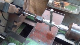
He made a tap follower to be able to tap the M3x.6 threads squarely.
1522313631308.jpg
Most of the work he did was by hand filing
1522313626477.jpg
 
View attachment 224558
Peter mistakenly drilled with a 5/32" dill bit for the M3 threads. So, we changed the FAB from an open-mouthed design to a tight-lipped design. He drilled a second hole 3/32" and tapped the M3x.6 threads. He turned the thumb screw. He heat treated it to give the small fine threads some extra protection against stripping.
He made a tap follower to be able to tap the M3x.6 threads squarely.

Congratulations :cheers: Singha, Chang, Leo, Archa? Now we can sleep again without worrying.


Back
Top