jscpm
Titanium
- Joined
- May 4, 2010
- Location
- Cambridge, MA
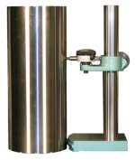
The standard way I have to measure right angles on blocks is that I stand the block up on a surface plate and touch a right angle standard to it, which is a cylinder. Then I shine a light and see if any light comes through.
This method leaves a lot to be desired. For one thing, it just measures the line of contact with the cylinder. Also, if you get light, it doesn't really tell you where the problem is, it just tells you that there is a problem.
Is there a better way to be doing this?
This method leaves a lot to be desired. For one thing, it just measures the line of contact with the cylinder. Also, if you get light, it doesn't really tell you where the problem is, it just tells you that there is a problem.
Is there a better way to be doing this?

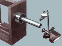
 but holding something up against and using "light" etc. isn't measuring. To measure then a tangible result is needed, not an approving nod.
")