QC Dude
Plastic
- Joined
- Aug 14, 2012
- Location
- Connecticut, USA
Hello all,
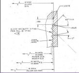
Anyone know a quick and accurate way to measure a a 10.375-8N BUTT-3 THD per MIL-S-7742. Print states: “Inspection of threads shall be by gaging method ‘A’ of MIL-S-8879 or MIL-S-7742, as applicable.” The minor diameter has a modification. I'll try to attach print.
I’ve read that spec and found “Methods A, B, and C have been eliminated.”, with no other methods mentioned other than a reference to FED-STD-H28/20. I then read the Federal Standard and it refers to "Gaging Systems 21, 22, 23". ...seems a bit vague to me.
SYSTEM 21 System 21 provides for interchangeable assembly with respect to functional size only. Functional size must be measured at the maximum material limit within the length of standard gaging elements. The characteristic known as NO GO functional diameter must also be verified. This can be accomplished by using fixed limit gaging or variable gaging with functional elements.
SYSTEM 21A (FOR METRIC THREADS IN ACCORDANCE WITH ANSI B1.18M) System 21A provides for interchangeable assembly with functional size verified at the maximum material limit using standard length gaging elements. This can be accomplished using fixed limit gaging or variable gaging with functional elements. System 21A also states that the minimum material limit (minimum pitch diameter) must be verified by inspecting two thread flank locations over the length of the thread. This can be accomplished by using variable gaging or thread roll snap gages with pitch diameter elements.
SYSTEM 22 System 22 provides for the interchangeable assembly with functional size verified at the maximum material limit using standard length gaging elements. This can be accomplished using fixed limit gaging or variable gaging with functional diameter elements. System 22 also states that the minimum material limit (minimum pitch diameter) must be verified over the full length of the thread. This can be accomplished using variable gaging with pitch diameter elements.
SYSTEM 23 System 23 provides for interchangeable assembly with functional size verified at the maximum material limit using standard length gaging elements and minimum material limit (minimum pitch diameter) must be verified over the full length of the thread. The gaging requirements for SYSTEM 22 would also apply here but in SYSTEM 23 other thread characteristics such as lead, flank angles, taper and roundness must have to be independently verified. Only thread characteristics, which are specified, will have to be inspected for SYSTEM 23 compliance.
**We don't have mechanical gages appropriate for the size. Should we use wires? Please advise.
Thank you!!
-Rich


