What's new
What's new

Measuring a hole location

MrEastwood31

Plastic
Joined
Feb 14, 2018
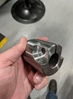
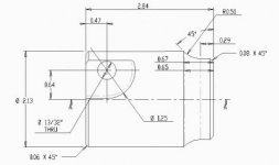
I am having a difficult time finding an easy solution to measuring this 13/32" bolt hole location. I have to measure the center of the thru hole off the face of the part (.47) and then measure the center of the hole to the center of the part diameter (.64), or at least off the OD of the part. I have scrubbed Mitutoyo and they have a centerline caliper but it is 18" long. Is there a company that has a caliper or micrometer that would allow us to quickly measure this dimension. See attached pic. bolt location.jpg
 
That's what I was thinking. Lay it in a V-block, level the hole using a pin, then touch off (electronic or manual height gauge) the OD and the pin and calculate. This part is round, right?
 
are you trying to measure in process or could you put the part on a surface plate?
if you can use a surface plate a high end height gauge will make quick work of the distance from the end to the center of the bolt hole
bolt hole offset from thru-hole center requires a little setup thought

if you need to do this with a caliper or the like, there are various attachments that go on digital calipers - you will want a digital caliper because you will set zero against some kind of first article.

look at flexbar, spi caliper attachments, or robin renzetis youtube video about custom calipers

UNIVERSAL CALIPER ACCESSORY KIT
VERNIER ADAPTER FOR 4/48 STEM


https://m.youtube.com/watch?v=5RZw5bJd5TQ
 
yeah, part is round. this is actually how we are doing it now. Just looking at other options that allow us to possibly do this in the cnc mill.
 
Likely I would set it in a V block and plate check it with a set of JoBlocks and a height gauge..
likely hard to find center of 13/32 so need to measure that to be sure...Having a good 13/32 reamer would make checking sure for long run of parts as a lot easier to find hole center with a true size hole...

Having a good machine table likely could plate check it off the table..

Ps a reamer would/might make a decent quick gauge for near centering the hole square to center line.

May have to consider OD tolerance and off C/l to not let build up of error make checking/holding size difficult
May have to set OD target tighter than allowed just to keep build up (accumulated) error in print..

Having a surface grinder handy might make rectangular step gauge to check with not making a Jo block set up (often) if a long run..good grinder hand should make a (CRS) gauge in perhaps 1/2 hour. I would take a piece of scrap from the bin and with a parting wheel and then a grinding wheel have quick gauge done.
 
are you trying to measure in process or could you put the part on a surface plate?
if you can use a surface plate a high end height gauge will make quick work of the distance from the end to the center of the bolt hole
bolt hole offset from thru-hole center requires a little setup thought

if you need to do this with a caliper or the like, there are various attachments that go on digital calipers - you will want a digital caliper because you will set zero against some kind of first article.

look at flexbar, spi caliper attachments, or robin renzetis youtube video about custom calipers

UNIVERSAL CALIPER ACCESSORY KIT
VERNIER ADAPTER FOR 4/48 STEM


https://m.youtube.com/watch?v=5RZw5bJd5TQ

Yes trying to measure in process. Reason being is that when we run this part in the mill, we have to make sure the bolt hole is correct because after we drill the hole, the part then gets a slot as seen in the picture. We found two items from mitutoyo but again they are huge. caliper2.jpgcaliper11.jpghub.jpg
 
A couple of questions you will need to answer before deciding which method to use is this: What is the level of accuracy required? Do you need to know actual measurements, or just confirm if the hole is located correctly?
 
Two place decimal on location and fractional hole? Don't overthink it. Check the first one and run the shit out of them. Check every 20 or so in-process.
 
Two place decimal on location and fractional hole? Don't overthink it. Check the first one and run the shit out of them. Check every 20 or so in-process.
Agreed, looks kinda like a thru hole for 10mm or 3/8".

Rig up a dial depth gage with a flat anvil to register on a pin in the hole? Measuring from the face would be dead simple, from the OD would require a little fiddlin to find TDC but that should go quick after the first few.
 
If you like the centerline caliper idea (I like some of the other ideas presented earlier better), you can modify a pair of 6", 8" or other more-convenient-than-18" calipers for this. You've probably seen centerline adapters for conventional calipers. Make something similar, sized to fit your hole, and cut down the back side of one caliper jaw as needed so the jaw will fit in the hole.

To use, open the calipers, put the modified jaw in the hole, put the other jaw against the OD or face as appropriate. Read off the value, then adjust for the adapter. For no-brainer, precompute the range of acceptable as-read values and write it into the test procedure so the operator doesn't have to do any arithmetic. Check the jaws-fully-closed reading periodically to protect against the adapter working loose from the modified jaw.
 
Does it intersect the thru hole?
If so, put a pin in your hole, then go/no go sizes into the bore. Provided that size is held consistently/tightly.

Make a gage where the outside have to slip over the od, and a pin has to go thru the gage and the part. Or just use side of the dia.

As others have said, a plate with a hole would square the part easily for further measurement. Maybe bolt two v blocks to the plate. Bolt that whole assembly against an angle plate and use a height gage. Or put dowels, or some stop to push the part against and trap it, and the pin has to go in.

A few ideas....
I don't know your environment, but personally, if jobs are being run by mainly operators, not really machinists, I prefer hard gages.
 
Not sure if you have found a solution to your problem yet, but our inspection system could find this dimension for you within seconds along with other external dimensions that you may be looking for. Not trying to promote my product, but I read your post and our system would find this dimension with ease. Let me know if your interested in finding out how our machine works?
 
Thanks everyone for all the ideas. I'm gonna try a few of these suggestions and find the best for our application. Just like any other machining, there's more than one way to skin a cat.


Back
Top