What's new
What's new

Parallelism of a Fixture Setup on an Instron

StudentMech27

Plastic
Joined
Oct 12, 2017
Hey all,

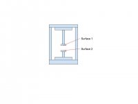
A friend asked me a question and I couldn't think of an answer off the top of my head so while I think on it I'd like to get your guy's thoughts. He is using an Instron Tensile Testing machine and has created a fixture set up for his specific test. He would like to know how he can test is the two surfaces are parallel to one another. I attached a rough picture of what he is trying to get at (as best as he could explain it to me). Thanks for any insight that you could give on this subject!

Thank you!
Untitled drawing.jpg
 
Where are the grippers, sample, and extensometer (if applicable)? Any other stuff that could interfere? As shown, a simple dial test indicator on a small flat slider block should work, adjust height to allow contact of the needle, carefully move the indicator along the platens and record the readings.
 
The distance can be controlled to be as large or as small as needed within reason (I think the max travel of the Instron is around 55in or so). He asked if we could get an accuracy of a thousandth of an inch. Now he is also on a budget and timeline so the accuracy might need to budge.

Thanks for your quick reply!
 
Where are the grippers, sample, and extensometer (if applicable)? Any other stuff that could interfere? As shown, a simple dial test indicator on a small flat slider block should work, adjust height to allow contact of the needle, carefully move the indicator along the platens and record the readings.

As much as I got from his explanation his fixture consists of two vacuum plates (represented by surface 1 and 2) and he just needs those to be as close to parallel as possible to ensure proper seal. I think the dial indicator would work if I could find a slider block small enough to sit on top of the plate.

Thank you for your response as well!
 
I work with this equipment a lot. Without a lot of detail on the application, I can tell you that most tensile testers are not designed for precision alignment. Most of the moving arms have all sorts of play if you touch or prod them.

Do they have a means in the fixture to adjust alignment if it is found to be out? Instead of hard locating both plates, allow one to float in its mount a bit and it will find parallel with its mate.

I just finished reviewing an Instron fixture that involves having a .020" pin on the upper arm push a part into a .021" hole. The only way to make it work was to mount the moving pin on a low friction linear ball slide for repeatable alignment and couple the slide to the load cell on the moving arm with in a way to allow lateral float to only transmit axial load.


Back
Top