What's new
What's new

Tricky measurement question

openhearth

Plastic
Joined
Sep 9, 2012
Location
Linden, NJ, USA
Hello to all other inspectors!!

I need to make an measurement of 46.250" with a bilateral tolerance of 0.005. The vernier I have goes to 40". Getting a longer vernier is not an option. I really don't want to use a tape. Anyone have any tips, suggestions, or whatever you would do in this situation? In advance, thanks for all answers.
 
If the component shape is suitable and you have a decently flat surface to work on arrange some sot of known length "hook" to transfer the out of range measurement into something in range. For example if its a flat bar with square ends you could use slips laid alongside to bring it into range, Hafta wring two other slips partially overlapping one end each of the transfer slips to register on the end. Not a nice way to proceed and certainly a job for the third best set. Doesn't have to be slips, something can be made to the lay on and hook thing or even clamp to the vernier jaws.

Another way is to use a trammel bar and three sets of points. One point somewhere in the middle two out towards the end set off the item to be measured. Now you can do it in two bites. Better if you have "flat one side" points like those in a gauge block clamp set for the ends. Again something can be made.

Have to be very careful with these sort of expedients as tolerances and errors can build up ferociously.

Clive
 
You really need to supply a bit more info to get a decent answer.

If it's a diameter, buy a Pi tape.

As others above, I'll assume it's a linear dimension. You can build a fairly expedient sort of go/no go gauge with a long bar and two ends, with one holding a +/- dial indicator. What's left is to have a standard to set the thing. This could be a known perfect part from the customer. It could be a very large stack of gage blocks if you have them. It could be two blocks made to .0005 standards on your newish lathe or mill. It could be a couple sets of jig bore standards bought off eBay and sent off for calibration. And so on.

Temperature is a concern over these long distances. Keep the machined part and whatever measuring scheme you set up at the same temp -- and about the same as your customer if you can.
 
Be a little careful of temperature variations, a 10 degree difference will change the measurement by about .0035"
 
Although temperature is a problem with this sort of measurement, don't forget to correct for the difference between calibration temperature of the vernier and shop temperature, ensuring your measurement is along the correct line can be a bigger one. Your tolerance allows you about one degree of angle error between vernier and object. Sounds plenty, that's getting on for 5/8 offset between the two ends. No one could be that far out. Surely.

A 40" vernier at full or near full extension is a tricky beast to handle at the best of times. The jaws are quite long making it harder to judge the actual line of measurement relative to the test object. Gordons dual vernier method sounds good but, having tried something very similar myself, you and your assistants can end up in a right mess. Four person job. One to hold the subject, one to hold each vernier and one to take the readings after eyeing things up to ensure that everything is held in proper alignment. In a makeshift like this its virtually impossible to hold the vernier just so and read it unless its possible to brace it against a solid lump of the object being measured. Its almost certain to shift if you try to lock it. Shift doesn't necessarily mean the reading alters but how are you going to know!

My feeling is that you will have to treat this as a scientific style measurement by establishing a solid technique and doing a few repeats to nail down the error band. More practical with solid transfer devices and a single measurement instrument. I've spent rather too much of my life measuring the improbable with the impractical and don't envy you one bit. If you are a normal "mic it and its right" guy the error bands are gonna horrify you!

Clive
 
I need to make an measurement of 46.250" with a bilateral tolerance of 0.005.

Translated to ISO-tolerances, that would be js9.
Well, IT 9 isn't that much a challenge, but with a vernier caliper it is.
The ratio of dimension to tolerance is 9200 : 1. Scaled down to an easier to grasp dimension of 100 mm that would be at about 0.01 mm. Well, that's the tolerance of a mechanical micrometer.

In other words, forget your caliper!


Nick
 
All great answers!!

Thanks to all whom have replied. You've provided alot of good information. I had't even considered the temperature factor in the measurement.

To all responders: Yes, that is a linear measurement, end to end. Thanks again!
 
Hello to all other inspectors!!

I need to make an measurement of 46.250" with a bilateral tolerance of 0.005. The vernier I have goes to 40". Getting a longer vernier is not an option. I really don't want to use a tape. Anyone have any tips, suggestions, or whatever you would do in this situation? In advance, thanks for all answers.

Just a thought.

Could you turn two bars to 23" each using the 40 inch vernier to measure these.

And use gage blocks between these two bars, for checking for the required measurement?

Another possibe check would be to drill and tap the bars ends with a tight fitting thread and use the thread pitch to wind them apart a know amount, before dropping in the slips?
 
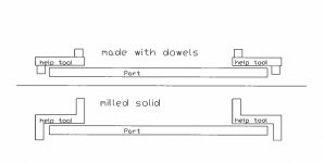
I know the parts probably is finished long ago, but for future similar measurement, perhaps a pair of these would help you out, milled from solid, or just reamed 4 holes in it, could be made in any length and width.
 

Attachments

  • 1.jpg
    1.jpg
    32.4 KB · Views: 358
When, as one poster did, mention how much a 10º difference mattered (C or F?) then this only really applies when there is that difffernce betweeen the measuring tool and the component. I doubt if that's often the case.
That's not quite true. The difference in thermal expansion coefficients between the material used for the scale and that of the part being measured ensures there will be an error if the measurement is made at any temperature other than 68oF/20oC. For a long part this can be significant.

Depending on what kind of steel the scale is made from, the coefficient of linear expansion could be anywhere between ~5 and 10x10-6 in./in.oF. For Al it's 12 in the same units so, taking the bottom end of the steel range to get the worst case, the difference between the two is 7. If the measurement is made after both the scale and the part have equilibrated at 78oF, the measurement error for a 40" part will be 0.0028". That is, because of the differential thermal expansion, if the part were measured with the same scale at 68oF it would find it to be 2.8 thou. shorter than if measured at 78oF. Another 10oF and this error would be larger than the accuracy needed by the OP (assuming the materials and values used for this calculation).
 
Da' :cheers:

Top marks from me for "thinking outside the box" but by the time it was made (plus materials and a clamp) and measured accurately to know how much to add onto the result, it'd probably have been cheaper to buy a large caliper.

Hvorhen i DK?

Gordon

Thanks :-)

I kind of agree, but i recently checked the price of a big vernier caliper, and they are pretty expencive, so if it is just for rare use i can understand if people hesitate to invest a lot of money in something they don't use often. But i must admit i have not tryed if i works in the real world :-)

Sjælland, Holbæk
 
Some notes on temperature as we have had this discussion many times with a customer.

Material makes all the difference. Van Kueren CARBIDE gage blocks and steel have different coefficients of thermal expansion. (same for Ceramic, and Cast iron)
Aluminum can be a real devil trying to hold +-0.003 on a 50.000" length tube with a .25" wall thickness that is machined from a 1.75" wall thickness.

Large part cross sections complicate matters as the surface can be one temperature and the core at a different temperature. large heavy walled parts must soak at temperature for a long time sometimes days to stabilize to the same temp as the tool.

Always recheck your measuring instrument before and after measuring. Holding ID mics for a few minutes in your hand can grow them a thou easily.

A question posed to us on a quality audit by this customer was this...
"If you measure a part with an outside mic and the mic reads 15.5000 and the mic was calibrated with a 15.0000" standard and the part, mic, and standard all are at the NIST temp. then you increase the temperature of all items by 100 degrees and remeasure after stabilization. what is the result?"
They were looking for us to tell them about differing coefficients of expansion. Instead I described to him that we would not know. because of the shape of an outside mic, the expansion will be non linear since one side of the bow is longer than the other. this will make the measuring faces out of parallel and render the mic inaccurate.
 
because of the shape of an outside mic, the expansion will be non linear since one side of the bow is longer than the other. this will make the measuring faces out of parallel and render the mic inaccurate.
There is nothing in the problem you just described that's non linear. Imagine the "bow" on a large micrometer that is made up of two horizontal arms 12" long and a vertical arm 24" long. When you heat this hypothetical square micrometer both 12" arms increase in length equally to, say, 12.1" and so the 24" arm increases to 24.2". This means that the horizontal arms remain parallel, and the only effect of the increase in temperature is to increase all dimensions by the coefficient of expansion of whatever material the micrometer is made from. The same would be the case for micrometer of the standard "C" shape.
 
In my limited experience in this context (extremes of temperature) it was the responsibility of the designer to provide dimensions at normal room temperature for the purpose of doing proper QC inspection. These dimensions might differ significantly from the "true" operating dimensions.

It's also the responsibility of the designer to choose appropriate materials such that their coefficients of expansion will guarantee the integrity of the final assembly at operating temperature.

All of this information is readily available in the engineering department, but is not available to the machine shop, nor should it be. It's the engineers' responsibility to produce drawings that can be manufactured and evaluated.

- Leigh


Back
Top