electron2002
Plastic
- Joined
- Dec 10, 2013
- Location
- Los Angeles
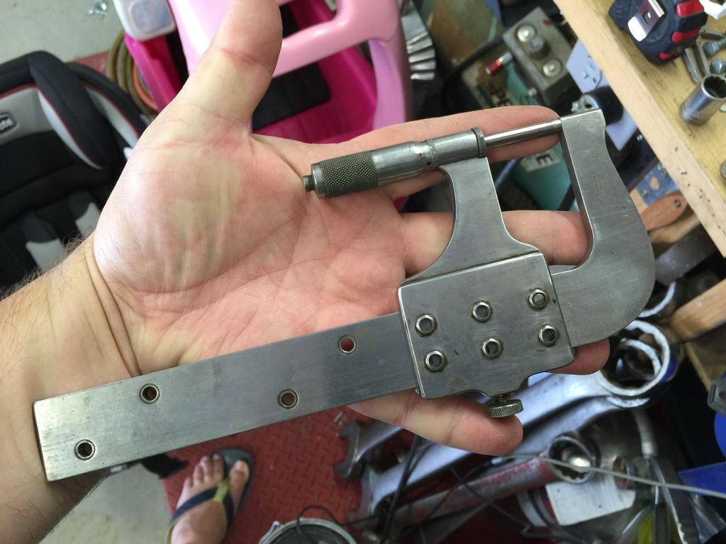
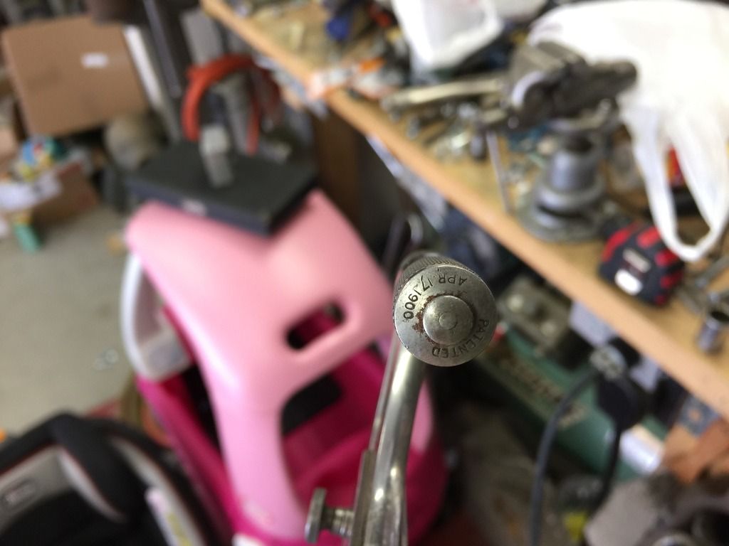
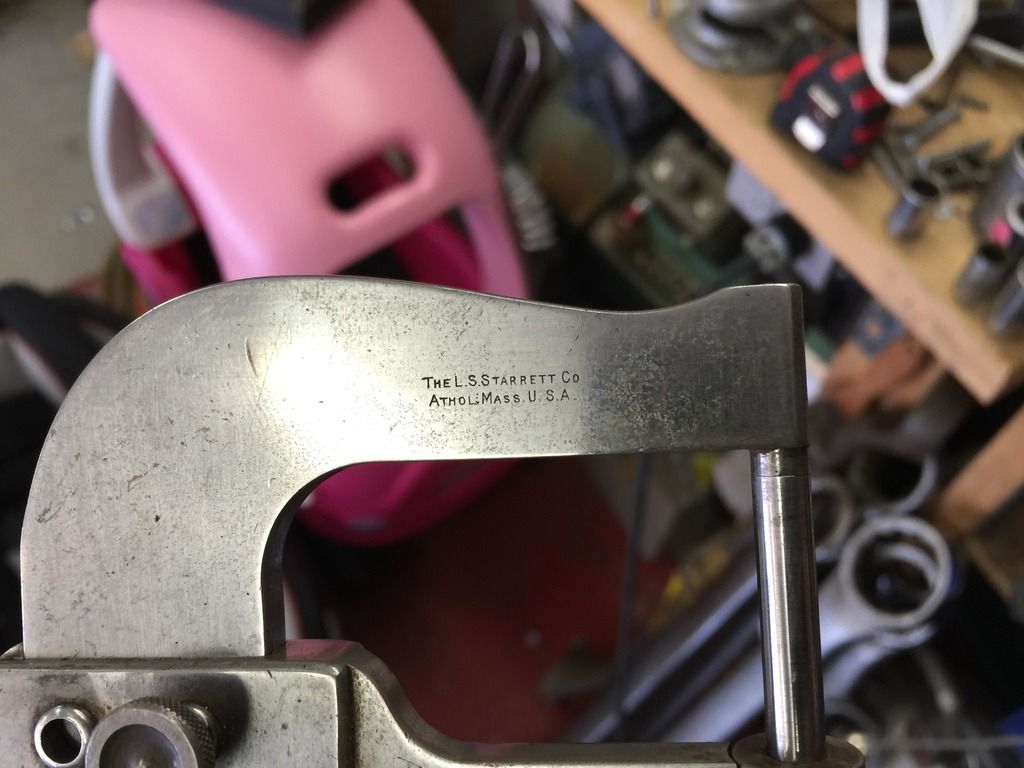
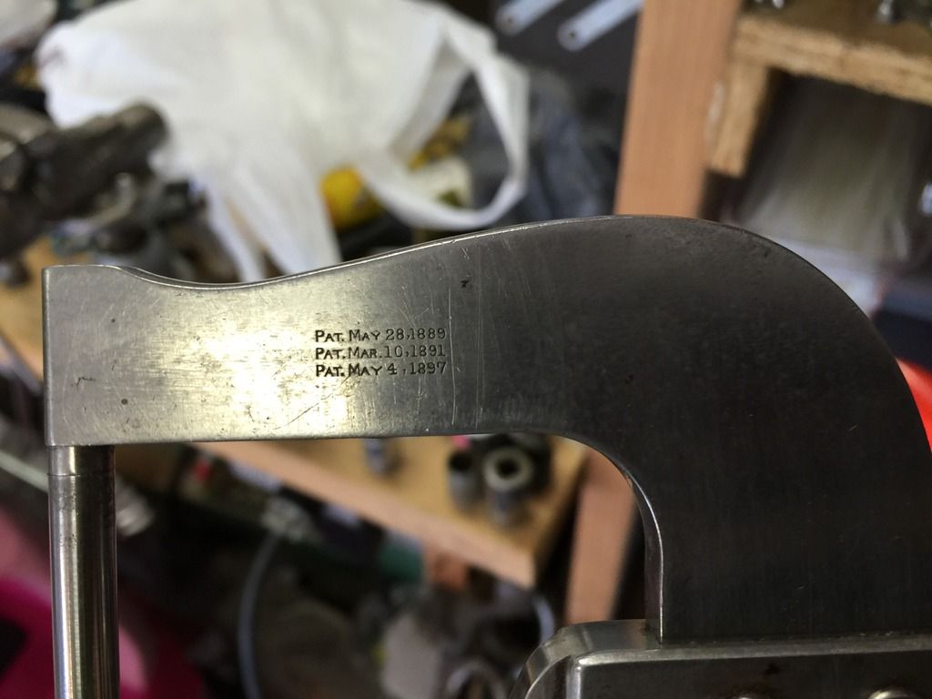
I came across a very unusual Starrett Micrometer this weekend, the likes of which I have never seen before. It is an adjustable 0-6" Micrometer, with adjustment achieved by siding the micrometer head down the body, indexing it using a pin and locking it with the thumb screw. There is no model number on the micrometer. There are four patent dates listed. The oldest 5/28/1889 would refer to patent #404057, which is a patent specific to the design of this micrometer. The other patents appear to be general patents regarding micrometers. The newest patent is 4/17/1900, so it can't be any older than that.
I can't find any reference to it in any old catalogs that I have found. The DATAMP results for patent 404057, shows another photo of one of these, but it appears to be missing the clamping shoe for the thumb screw.
I can't find any reference to it in any old catalogs that I have found. The DATAMP results for patent 404057, shows another photo of one of these, but it appears to be missing the clamping shoe for the thumb screw.
