What's new
What's new

10ee DC Panel Problem Solved

lohring

Plastic
Joined
Apr 27, 2013
Location
Oregon USA
After running fine for the past year, my 1947 square dial, motor generator, 10ee lathe's spindle started to slow down then return to the set speed. It rapidly got worse and worse. I spent some time on this forum studying the excellent posts on the electrical system and decided it had to be the 2000 ohm resistor at the top of the DC panel. I removed and tested it, and the resistance was fine. However, while removing the resistor, I noticed that the screw holding one of the wires was loose. I reassembled the resistor, tightening everything and the lathe ran fine.

The moral of all this is despite the appearance, the motor generator DC drive system is electrically simple and tough. Check out the simple things before doing something drastic. This forum has some great wisdom on the machine.

Lohring Miller
 
Screws on contactor overload relays will drive you batty. It is good practice to check tighten ALL terminal screws in industrial wiring cabinets every few years if you can get downtime. BTDT and I have a few merit badges to show for it.
 
Unfortunately, the problem wasn't that simple. After running a while the lathe began to slow down then pick up again like someone turned off the motor then turned it on again. I decided to replace the resistors, but it only worked for a short time.

The problem seemed to go away at the highest spindle speed setting, but returned with a vengeance until the spindle motor stopped completely. The motor generator runs fine, and both the forward and reverse contactors pull in. I checked the resistance of the variable resistors and the left one in the picture varies from a few ohms to over 80 ohms. The right one shows no resistance either across the whole coil or from the wiper to the end of the coil.

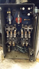
Below are pictures of my DC panel front and back as well as the variable resistors. Is the variable resistor the problem? What should I check?

Lohring Miller

20161216_150824.jpg 20161216_150900.jpg 20161216_150957.jpg
 
If the variable resistor is open infinite ohms it will need to be replaced before any more troubleshooting can be performed.
 
I checked the resistance of the variable resistors and the left one in the picture varies from a few ohms to over 80 ohms. The right one shows no resistance either across the whole coil or from the wiper to the end of the coil.
Measurements were taken with them fully disconnected? OR still in the circuit?

"Loose" IIRC, they are about 380-400 Ohms - MG-era.

I have '42/'43 era spares here if it turns out you need them.

Bill
 
I am certainly no electrician ,but having run mostly old equipment(I'm cheap)found many many instances where electrical problems boil down to corrosion.going over the connections,tightening occationaly would go a long way in reliability.:D
After running fine for the past year, my 1947 square dial, motor generator, 10ee lathe's spindle started to slow down then return to the set speed. It rapidly got worse and worse. I spent some time on this forum studying the excellent posts on the electrical system and decided it had to be the 2000 ohm resistor at the top of the DC panel. I removed and tested it, and the resistance was fine. However, while removing the resistor, I noticed that the screw holding one of the wires was loose. I reassembled the resistor, tightening everything and the lathe ran fine.

The moral of all this is despite the appearance, the motor generator DC drive system is electrically simple and tough. Check out the simple things before doing something drastic. This forum has some great wisdom on the machine.

Lohring Miller
 
If the variable resistor is open infinite ohms it will need to be replaced before any more troubleshooting can be performed.

I should have been more clear. It showed ZERO resistance both from the wiper to the end and across the coil winding. This didn't make any sense since the other resistor showed what I considered to be normal behavior. I did not disconnect anything (yet) so I probably wasn't measuring the resistor's resistance. Does anyone have a wiring diagram for this particular DC panel? The ones I find on this forum seem different in that they show capacitors that I can't find on my panel.

Lohring Miller
 
A field acceleration relay can cause that problem - if it pulls in at a high speed it'll give you a full field instead of the low field, and the motor will slow. If it drops out after the motor slows the motor speed will increase. Often it'll cycle like that giving you a drive that goes whirRRRRRwhirrWHIRRR. You can check to see if it's the problem by putting an insulator between the contacts on the FA relay and running the drive up carefully from low to high.

The FA relay can also misbehave with a bad resistor.

I'm not sure how to calibrate the FA relay, I suspect that it could be done with a calibrated current but you might just set the tension so it closes until a speed change from 100 to 1500 rpm is complete and doesn't when you change from 1200 to 1500 (or some other appropriate range).
 
I think Russ is right. That sounds like an FA (Field Acceleration) relay problem. (The FA relay is the one in the upper left corner of the panel.) It's supposed to close when the armature current is high, to apply full field to the motor. When it closes, it shorts across the motor rheostat (which acts to reduce or weaken the field). If the FA relay stuck closed, it will keep the motor rheostat shorted out and cause the reading that you have. The motor rheostat is the one with two leads, labeled E1-2 and F2. You can put a piece of cardboard between the contacts and see if that changes your rheostat reading.

Disconnect one of the leads from the rheostat before testing it. It should read zero Ohms for half the rotation, then increase to about 400 Ohms (I think, going from memory here).

Send me an e-mail and I'll send you my color-coded wiring diagram for that panel. (Right-click my user name and select the e-mail option.)

Cal
 
More troubleshooting:

1. Disconnecting the end (not wiper) wire on the right rheostat gives a resistance that goes from a few ohms for a while (1/2 way?) then increases to around 190 ohms.

2. The resistance between the wiper and disconnected end wire is about 0.1 ohm, the same as with the wire connected. It doesn't change when closing the FA relay.

3. When the spindle is run the motor pulses on for a few seconds to the set rpm then coasts down.

4. The FA relay kicks on briefly during acceleration then drops out.

5. Holding the FA relay closed doesn't change the pulsing behavior.

6. The pulsing gets worse with continued operation until the motor finally stops and won't start again.

7. The motor then starts up the next day after a night in the cool shop with the same behavior.

I'll trace out more of the wiring when I get the wiring diagram. (Thanks everyone) What other trouble shooting would help?

Lohring Miller
Check your exciter voltage when it does run and see it it is pulsing.
 
I encountered a somewhat similar problem that turned out to be a generator brush that was stuck and only contacting in a small area at one end. Wiggling the brush cured it. Make sure the brushes have enough length left and are free in their holders.

Bill
 
Lohring,

I emailed you the diagram just before you posted today.

Definitely check the brushes and commutators on the exciter, generator and spindle motor. The commutators should be the color of an old penny with no black bars or radial streaks. Look for sparking when the MG and spindle motor are running. You should only see a tiny pinpoint spark at each brush.

Checking the field and armature voltages at midway on the speed control can tell you which half of the system is acting up. Set the speed control to mid way, which should put the wipers on the rheostats at 12 O'clock.

Read the field voltage between F2 and E2 on the terminals at the bottom of the DC control panel. It should stay at about 115 VDC.

Read the armature voltage between terminals A2 and A1. It should stay at 230 VDC.

Make sure that you correctly identify the terminals on the DC panel when you are making measurements. The terminal label should be above the terminal and should match the tag on the wire. F2, A2 and A1 are on the top row of terminals. E2 is on the left end of the middle row.

Cal
 
The DC motor looks like the brushes were replaced recently and move freely. My lathe doesn't have an exciter. I can see where it mounted on the motor/generator. I think it has been replaced by a bridge rectifier. I haven't checked the generator brushes, but that sounds like the next area to look at. Fortunately, I think I have some replacements. I'll be away from my shop until Friday, so don't expect a report for a few days.

Thanks again for the wiring diagram. The color really helps trace out the connections.

Lohring Miller
 
I finally got back and made some of the suggested checks. I set the speed control to the middle of its travel.

The A2 - A1 voltage is 0 with the spindle motor off, goes to 230 volts with the motor on but drops off as the power pulse fades.

The F2 - E2 voltage is 111 volts with the motor off but drops as the motor runs.

The spindle DC motor commutator has minimal sparks at startup but starts sparking as the power drops.

The DC generator commutator behaves the same way.

The brushes look like they have been replaced recently. I have extra DC motor brushes but no new generator brushes. The motor/generator has no exciter. It has been replaced by a bridge rectifier.

However, more attempts to measure the voltages reveled the problem. With only the motor/generator running, lots of smoke started to come out of the transformer ahead of the motor generator.

Would anything be damaged by this? What else should I check? What are good sources for a replacement?

Below are pictures of the motor/generator panel and the transformer. Note: the transformer was correctly wired for 220 volt operation despite the label.

Lohring Miller

20161225_112236.jpg 2014-04-14_17-08-54_22.jpg
 
More guessing, that isn't a very large transformer and it may not be able to supply enough current. Next guess is a shorted rectifier. They are cheap and I would get one of the higher current variants because it may not have a very good heat sink. The goo around it looks more like RTV than heat sink compound, not a good idea.

Bill
RTV rubber most are good conductors of heat but the steel panel is not a good heat sink and worse than the RTV. The transformer could only supply about 3 amps.
 
However, more attempts to measure the voltages reveled the problem. With only the motor/generator running, lots of smoke started to come out of the transformer ahead of the motor generator.
Surely you are not telling us that 350 VA transformer provides the sole and only power path from one of:
[ Utility 3-Phase | 3-P gen set | Phase Perfect | RPC ] to the 3-P motor driving the MG?

350 VA is not even ten-percent of what the MG 'motor' needs, (it is 4 1/2 HP or thereabouts) .
Even so, a three-phase transformer is wanted there. Around 6 kVA to 7.5 kVA or so.

Check the wiring again. This can't be right.

It isn't even close enough to relevant to be classed as "wrong".

Bill
 
The transformer rating was my thought as well. When I got the lathe it had only partially been converted to 220 volts from 408 volts. The DC panel was not getting enough voltage to reliably close the contactors. Rewiring the transformer fixed that problem but doubled the transformer current. Even so, it ran fine for over a year. The transformer with rectifier conversion was done long ago, probably at Boeing, to replace the exciter. I'll search this forum for details on how to do that replacement, but would appreciate any help. It seems that I should replace the rectifier as well. Could the generator section of the motor generator be damaged?

Lohring Miller


Back
Top