upfberg
Plastic
- Joined
- Apr 28, 2015
- Location
- North Henderson
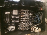
Hello I have a 10EE that am in the process of getting it up and running. I have the motor generator and the drive motor out and at the motor shop currently. they are checking it out and making sure that its good to go. but in the mean time i think a caused a little hiccup. the pictures will explain more but maybe you guys can lead me in the right direction. there is a switch box next to the drive motor behind the end panel that contains the forward and reverse switch that controls the drive motor. behind this box there is some wires that appear to be isolated by ceramic insulators. this box was bumped some way shape or form and a wire was broke. i think this is a heat sink of some sort. can i twist the wire back together and be short a loop or should i do something else. any thoughts would be appreciated. thanks brian