Ok, after getting some sleep (giving electrical advice when tired is just a bad idea

). There are basically two ways to set up the wiring. One will require you to push Stop between directional changes, the other will let you go directly from forward to reverse (plug reverse). Its a little more work but personally I would go for option two, Just my personal preference. However, either way, you seam to be missing some wires.
Option one:
Requires four wires: Power in, Power out to hold, power out to Fwd, power out to Rev
Assuming that power for the mag coils is being supplied from a transformer, basic wiring will be something like this: One wire from the xformer will go directly to one terminal of each of the mag coils. The other wire from the xformer will be Power in, and will go to terminal (10). A Jumper will go from terminal (9) to (8) and (4). Power out to Fwd will connect to terminal (3) and power out to Rev will be connected to terminal (7). Finally power out to hold will also be connected to terminal (9).
Back to the mag switches. The power out to hold wire will be connected to one terminal of both of the hold (auxiliary) switches. The other terminal of each of the hold switches will be connected to the second terminal of their prospective mag coils. Finally the power out to Fwd and Rev wires will also be connected to the second terminal of their prospective mag coils.
If the hold switches have both NC and NO contacts you will want the NO contacts.
Option two:
Requires five wires: Power in, Power out to Fwd, Power out to Fwd Hold, Power out to Rev, Power out to Rev Hold.
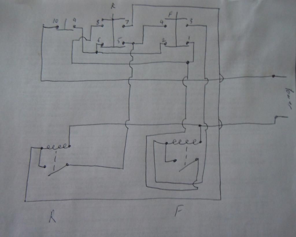
Assuming that power for the mag coils is being supplied from a transformer, basic wiring will be something like this: One wire from the xformer will go directly to one terminal of each of the mag coils. The other wire from the xformer will be Power in, and will go to terminal (10). A Jumper will go from terminal (9) to (6) and (2), another jumper will go from (5) to (4), and another jumper will go from (8) to (1). Power to forward will be connected to terminal (3), and power to Reverse will be connected to terminal (7). Finally, Power out to Fwd Hold will be connected to terminal (1), and Power out to Rev Hold will be connected to terminal (5).
Back to the mag switches. The power to Fwd hold wire will be connected to one side of the hold (auxiliary) switch on the forward mag switch, and the Rev hold wire will be connected to one side of the hold switch on the reverse mag switch. The other terminal of each of the hold switches will be connected to the second terminal of their prospective mag coils. Finally the power out to Fwd and Rev wires will be connected to the second terminal of their prospective mag coils.
Again if the hold switches have both NC and NO contacts you will want the NO contacts.
This really is easier to see than to explain. There is a decent schematic here ->
http://literature.rockwellautomation.com/idc/groups/literature/documents/wd/gi-wd005_-en-p.pdf
Pages 27 and 28 of the pdf.
Here is a quick drawing I did for option two:
Hope this was more helpful than confusing,
Jim


") .
.
 .
.


