What's new
What's new

1943 10ee

maynah

Stainless
Joined
Mar 24, 2005
Location
Maine
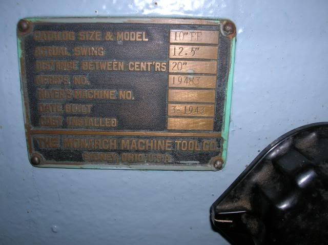
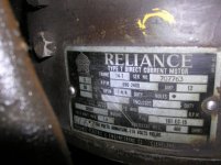
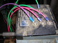
I recently purchased a 1943 round dial, serial #19483. I really had to decide if I was taking on more than I should with this lathe. I was only largely unsure of my skill with the mechanicals, infinitely unsure of the electrics. I didn’t pay a great amount for it so I took the gamble. I started reading the first post from the Monarch forum dated January 10, 2001, and worked my way forward in time to the present. I started a Word file and every post that seemed relevant; I put the link in my file. I didn’t see any retrofit drive that looked like mine. So what do I have? (see photo album) It does run on 220 volt single phase. The owner started it up and the spindle ran forward and reverse, the feeds worked, but most of my attention was on the fireworks show coming from the brushes on the DC motor. And the smell took me back to my childhood, running HO trains and HO cars. He didn’t take the speed up too far and I was glad he shut it down. It did change speeds with either the lathe speed change knob, or the black knob next to the data plate.

It does have a few good points going for it. Long cross-feed slide with dovetail, taper attachment, bottom half of the carriage multiple length micrometer stop, Aloris AXA–T tool post, I’ve never seen a one sided post, it even has the tailstock dauber. It also came with a 6” 3 jaw and 8” 4 jaw chucks, a face plate, and the Monarch operators manual, although for an earlier lathe. I’ve never seen another spindle lock handle like is on my tailstock. Is that just a convenient replacement?

I have a ton of questions. The major two are:
Is this drive a good way to run the lathe?
Is the rest of the lathe in good enough condition to put money and time into it if it needs a new drive?

My ham handed tests show a bed, (or maybe saddle), with almost .003” wear, and I’m still playing with a spindle check. Someone has been in the spindle before judging by the buggered SKF lock nut, (I’m looking at the manual hoping I’m getting the names right). I’m guessing before it got the baby blue paint job it was pretty rough looking. But there are signs of hope. The tailstock had about .160” of play working the handwheel. I took it apart and it had been repaired badly at the spindle nut-lock nut. A little fiddling and it’s now .018”. I’m hoping some other slop in other assemblies may be able to be fiddled out. Going through other posts it seems even well worn lathes are still very good lathes and I wouldn’t mind that.


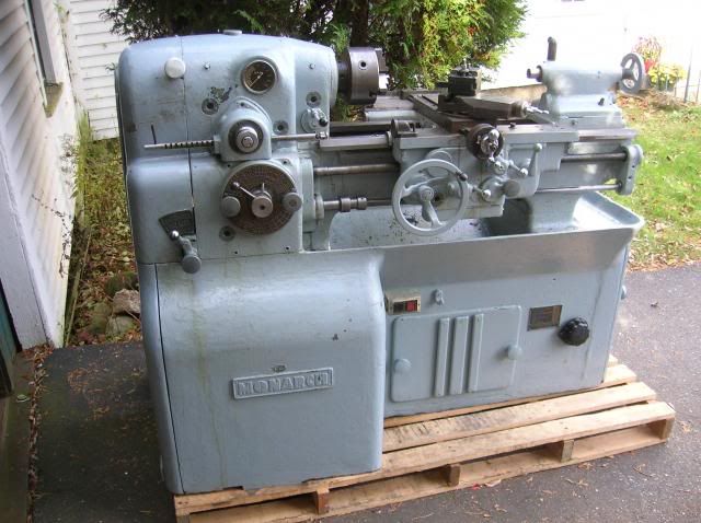
Below is the lathe and the link is to an album with all my EE pictures of the lathe. From the delivery, to putting it to bed for the winter in my barn. My shop has a wooden floor that is not up to the task of supporting the lathe. So I’ll have to wait until spring so I can sort that out. The pictures with the dial indicator are what happens when we get big temperature swings for a few days in the fall and spring. I removed the rust with 4 ought steel wool and coated everything in grease. For now, it sleeps in the barn until spring.

Thanks for looking and any comments.
Jeff Ward

1943 Monarch 10EE Photos by rustorater | Photobucket

DSCN5188_zpsd687abe8.jpg
 
Looks like it's had a hard working life topped of by a make-up paint job but on the whole not too bad. The broken gib roller could be due to a build-up on the underside way, mine didn't have any significant apparent crud on it until I got a scraper under there and found years of compacted grime so hard and smooth it was difficult to tell it from the metal.
 
Bill,

I think you nailed it.

Jeff posted nice, high-resolution (2300x1777) photos to the photobucket site. Use the zoom feature to get a better look at things.

The variable transformer is a Superior Electric Powerstat, model 236B-2. It's very similar to one that recently sold on eBay, a 236BU:
eBay #281197902458 - Superior Electric Powerstat, model 236BU

It's a 240V, 10A (2.8 kVA) model with 6 taps on the winding.
Here's a datasheet: Superior Electric Powerstat, model 236 datasheet

If you look at the photo for the MG terminal panel, you can see one bridge rectifier module mounted onto the right of the terminal strip. The photo of the powerstat shows a larger rectifier mounted on the back side of the MG terminal box.

My best guess, based on the photos, is that 240 VAC is connected to powerstat terminals 1 & 2. Terminal 3 (the wiper) probably provides 0-280 VAC to the big rectifier on the back of the terminal box. Terminal 6, a central tap, probably provides about 120 VAC to the small rectifier. The big rectifier seems to be connected to the spindle motor armature terminals; the small rectifier connects to the E1 & E2 terminal, which powers the DC panel and the spindle motor field. The big Ohmite potentiometers are still in place. Unless the field pot has been disconnected, it should still work to provide field weakening.

Jeff,

Great writeup and photos!

I don't see any reason that this shouldn't work to power the drive and even give you close to full speed. You'll have to be the judge of whether or not it will meet your needs.

Your brushes are definitely shot; you'll want to order a new set from Monarch before you try to run the machine. Your commutator looks pretty dark, it may need a touch up from a commutator stone as well.

There are several things that I would change before running the machine, including adding MOVs to protect the rectifiers, adding some fuses and verifying that the overload heaters in your contactor are correctly sized.

Can you take any more photos before spring? Can you get the build date and serial number (MFGR'S NO.) from the brass plate on the base, below the tailstock?

Cal
 
...

I had at one time looked into used, 'legacy' Variacs, ... and figured I needed at least a 4 kVA rating ...

2.9 kVA is a mite on the sparse end for a 3 HP final-drive motor, ...
I agree. The DC panel and field draw about 2A. Since they share part of the winding with the armature supply, the armature can only draw about 8A before you're in an overload situation. But 8A to the armature may be all he needs and more. I'd handle that by choosing 10A overload heaters for the AC contactor.

It will be very interesting to see how the machine performs.

Cal
 
I recently purchased 10ee built Jan of 1944 serial #24843. It was somebodys lawn ornament? I have been reading these post for about a year now trying to get all my ducks in a row before i start taking it apart. Anything you would ever want to know is within these pages. 100_1659.jpg
 

Attachments

  • 100_1742.jpg
    100_1742.jpg
    94.8 KB · Views: 639
  • 100_1700.jpg
    100_1700.jpg
    99.3 KB · Views: 683
Thanks for all the interesting expertise. But I can cannot over state my electrical ineptitude. I will take more pictures. Anything with a wire running to it. I may get lucky and shoot a few that will give you more information. And I need to start making a list of parts to get from Monarch, way wipers, brushes, carriage bearings, etc.

Cal, here's a picture of the data plate. I forgot to put it in the album, but it's there now.

DSCN5224_zps8e2e0000.jpg
 
I took a few pictures today. I need to poke around a little more and follow wires, but to be honest, it was a little chilly in the barn.
Also the wires are very stiff from the cold and I was afraid to move them much. The hinged electrical panel on the headstock end would
only open a little more than halfway before it would get hard to move. I've got to wait for warmer weather to explore more.

Can the work on the brushes be done without removing anything more than the drive belt?
 

Attachments

  • DSCN5317.jpg
    DSCN5317.jpg
    96.6 KB · Views: 345
  • DSCN5322.jpg
    DSCN5322.jpg
    88.4 KB · Views: 395
  • DSCN5323.jpg
    DSCN5323.jpg
    97.2 KB · Views: 402
I took a few pictures today. I need to poke around a little more and follow wires, but to be honest, it was a little chilly in the barn.
Also the wires are very stiff from the cold and I was afraid to move them much. The hinged electrical panel on the headstock end would only open a little more than halfway before it would get hard to move. I've got to wait for warmer weather to explore more.
...
What we really need is to trace out the wires connected to the variable transformer, back to the terminal panel under the chip pan. Good photos inside the DC control panel (big box by the spindle motor) will be helpful to determine if anything there has been modified.

The easiest way to get the DC panel out of the way is to remove the hinges and lay if face down. Take good photos of the back if you do that.

Cal
 
Took some more pictures today. I did lay the DC panel down. I think I got a rectifier. Took some of the switch by your left knee when operating the lathe. The terminals are installer marked in the box under the chip pan, I think you can read them. One wire popped off the rectifier when I was screwing blocking to the pallet to move the lathe. I haven't put it back on yet, but I think it goes to the empty yellow terminal on the rectifier. The last 8 pictures in my album are the new ones. I'll trace each wire from the Variac and add shortly.
 

Attachments

  • DSCN5327.jpg
    DSCN5327.jpg
    89.4 KB · Views: 444
Here's my crude diagram where the wires go. There is a little black cube in the junction box that may be part of the rectifier that is on the back side of the box.
Under the AC2 wire it says "silicon power cube."
The link to the album is in the first post.
I'm calling the 5 terminal device a rectifier but I don't really know that's what it is.
Thanks for everyone's time.
 

Attachments

  • img008.jpg
    img008.jpg
    75.6 KB · Views: 412
  • DSCN5329.jpg
    DSCN5329.jpg
    96.7 KB · Views: 370
  • DSCN5195.jpg
    DSCN5195.jpg
    97.4 KB · Views: 382
From looking at what you drew the person who wired it is using terminal 6 on the Variac as a center tap to provide 120Volts ac to the square rectifier the rectifier then supplys DC to the existing E1 and E2 if you look at the existing monarch wiring diagram it should provide the field weakening and power for the relays from E1 and E2. Terminals 3 and 5 of the Variac provide the variable AC to the 5 terminal rectifier which then provides the variable DC for the armature. Terminals 1 and 2 on the Variac should be the 240 volts ac input. Do You have the monarch wiring diagram? If you do check and see if there are any modifications to the original control circuit or just the power supply circuit. Bob
 
The reason it looks like a crydom ssr is part of silicon power cube was acquired by crydom. Crydom has a 5 terminal 3 phase rectifier that looks exactly like this one without the labels on top. Bob
 
... a 230 VDC Armature, 110 VDC field ex S/N 17120 SEP 1942 'Round dial' panel I am packing up to send to J Lewis, but if you do not already have photos of one of those, I could give it a try. Any special close-ups wanted?

Bill
Bill,

I would be grateful for some high-resolution pictures of the panel. Here's my wish list:
  • cover
  • inside front
  • back
  • top third of panel
  • forward/reverse contactor assembly
  • terminals on the bottom
  • slightly angled views of the back, from either side of the braking resistor, so that wires under the resistor can be traced.
  • close-ups of the tag on the cover, tag on the F/R contactor and any other component tags.

You could e-mail them to me or put them on one of your ftp sites.

Thanks!

Cal
 
If the 5 pin device is a 8510 that's definitely not the best thing to use if it's a M50 series it is a great device to have. It looks physically like a m50 series crydom not an 8510 but the 8510 marking show otherwise. Some good pictures of all sides to make sure there are no other markings would be very helpful. Worst case you may have to put a meter to it to see for sure what it's doing ( put ac in on your ac terminals and see if you get DC out the + and - ) then you are either good to go or need to replace it. Bob
 
Cal I looked at the link Thermite provided. But it's not the same as what the pics show. I'm pretty sure it is the same as a m50 series crydom silicon rectifier with 3 phase input and DC output. If so it can pass voltages between 600 and 1000 volts with an amperage between 50 and 80 amps. the breakdown voltage on these is between 1.5 and 2.5 KV for a short duration. I think the code he found 8510 is a manufacture date code 2digit year month. If maynah can find anything else on the device it would be helpful. If I remember right the part number is on the opposite side from that 4 digit code. Bob


Back
Top