What's new
What's new

1952 10ee

Nightshift

Aluminum
Joined
Sep 22, 2007
Location
London, ON
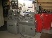
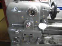
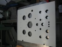
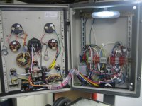
Sorry for the delay in getting some pics up of my '52 EE (SN EE-36004). I've had several people here requesting and I'm finally getting around to it. It's been totally dismantled over the past 9 months with everything gone over with a fine tooth comb. Very little had to be done to this one, other than stripping off 4 previous paint jobs and repainting and a complete re-wire to eliminate the oil-soaked original wiring and controls. Like my other refurbs, I like all the switches and buttons in one place, so I built a new Allen Bradley control panel during the re-wiring. This one is still powered by the original Alliance 3hp DC motor, but I'm using a custom-built DC drive controller instead of the original AC motor/generator/exciter assembly. You will also notice I have raised it up 4.5" and hidden the riser blocks with a skirt that follows the shape of the base casting. It puts the floor to spindle measure at 48.5" which is much more comfortable for me. And I think the skirt makes it look like something Monarch might have done if they would have offered a riser kit option. The lathe does not have a taper attachment, but is pretty much fully tooled with everything else including 8" and 5" 3-jaws, 8" 4-jaw, 11" face plate, Hardinge Sjogren speed chuck (full 42-set 2J collets), Jacobs Rubberflex speed chuck (14 collet set), Aloris BXA and AXA tool posts, steady rest, etc.

I also have the original manual, documentation and wiring blueprints which are in pristine condition. The original owner had the good sense to photocopy everything when the machine was new, and provide the photocopys to the shop workers in order to keep the original documents from getting dirty. As all of you know, the 10EE is a beautiful lathe to operate, and this one will be in my shop for a long, long time! Cheers, Bill
 

Attachments

  • - Monarch 10EE (1952) SN 36004 20.jpg
    - Monarch 10EE (1952) SN 36004 20.jpg
    93.9 KB · Views: 1,060
  • - Monarch 10EE (1952) SN 36004 21.jpg
    - Monarch 10EE (1952) SN 36004 21.jpg
    92.5 KB · Views: 1,126
  • - Monarch 10EE (1952) SN 36004 22.jpg
    - Monarch 10EE (1952) SN 36004 22.jpg
    85.7 KB · Views: 929
  • - Monarch 10EE (1952) SN 36004 23.jpg
    - Monarch 10EE (1952) SN 36004 23.jpg
    86.9 KB · Views: 1,577
  • - Monarch 10EE (1952) SN 36004 24.jpg
    - Monarch 10EE (1952) SN 36004 24.jpg
    89.8 KB · Views: 1,371
For tooling storage, I'm using an old Beach 5-drawer roll cab with a 2-drawer riser which seems to hold the most of it.
 

Attachments

  • - Monarch 10EE (1952) SN 36004 26.jpg
    - Monarch 10EE (1952) SN 36004 26.jpg
    90.1 KB · Views: 4,436
Nice Work!!

... This one is still powered by the original Alliance 3hp DC motor, but I'm using a custom-built DC drive controller instead of the original AC motor/generator/exciter assembly. You will also notice I have raised it up 4.5" and hidden the riser blocks with a skirt that follows the shape of the base casting. It puts the floor to spindle measure at 48.5" which is much more comfortable for me. And I think the skirt makes it look like something Monarch might have done if they would have offered a riser kit option. The lathe does not have a taper attachment, but is pretty much fully tooled with everything else including 8" and 5" 3-jaws, 8" 4-jaw, 11" face plate, Hardinge Sjogren speed chuck (full 42-set 2J collets), Jacobs Rubberflex speed chuck (14 collet set), Aloris BXA and AXA tool posts, steady rest, etc.

I also have the original manual, documentation and wiring blueprints which are in pristine condition. ...
Hi Bill,

Great job on the refurb! I especially like your riser system; you're right, it looks original. What do the hidden riser blocks consist of? I'm 6'2", so I've considered making cast concrete risers for my machines to get them up to a comfortable height.

I would also like to hear more about your custom DC control panel. It also looks original and the "Monarch DC Drive" plate is a very nice touch!

Does any of your tooling have stamped serial numbers that match the machine's s/n? Does your documentation indicate what tooling the machine left the factory with?

Cal
 
Now you're just showing off! Seriously, that should be a heirloom to be touched by many generations to come. I had to look at the pics in the other room, my South Bend started oiling itself when they popped up. It looks like you ride a Harley, so you might know a thing or two about what I am talking about!;)
 
I especially like your riser system; you're right, it looks original. What do the hidden riser blocks consist of? I'm 6'2", so I've considered making cast concrete risers for my machines to get them up to a comfortable height.

I would also like to hear more about your custom DC control panel. It also looks original and the "Monarch DC Drive" plate is a very nice touch!

Does any of your tooling have stamped serial numbers that match the machine's s/n? Does your documentation indicate what tooling the machine left the factory with?

Cal
Thanks for your comments Cal. I'm also 6'2" and hence the reason I raised the EE. There are 3 risers which are 6" x 6" x 0.25" wall square tubing about a foot long. I welded 0.25" plates on each end of the risers to close them in and hence significantly strengthen the tube. I probably didn't need to do that because there would only be 1/3 of the weight, or a little over 1,000 pounds on each riser, but this IS a Monarch, so why not beef them up! They are positioned under each of the 3 pads on the base. I ran a cap screw down an existing hole in from the inside of the base into each riser (I had drilled and tapped a hole in each) so when I move the lathe around with my pallet truck, the risers stay in position with the base. Then I just made a 4" wide skirt out of 0.125" metal to follow the outside shape of the base. The skirt is just a bunch of pieces all welded together and only covers the front and both ends. Once the lathe was in position and leveled on the the risers, the skirt just slides under, and then I attached it with a couple button head allen bolts.

I'll post another note with some pics of the DC panel.

My serial number does not appear on any of the tooling ... there are different numbers of course on the back of each, but they are all different, so I assume they might be part numbers? Two of my chucks are P/B but I don't think any of them are original. I also didn't notice anywhere in the documentation to indicate what came with my lathe from the factory. Bill
 

Attachments

  • Monarch 10EE Skirt 1.jpg
    Monarch 10EE Skirt 1.jpg
    87.3 KB · Views: 824
  • Monarch 10EE Skirt 7.jpg
    Monarch 10EE Skirt 7.jpg
    101.2 KB · Views: 723
I would also like to hear more about your custom DC control panel. It also looks original and the "Monarch DC Drive" plate is a very nice touch!
Basically what powers this lathe now is DC motor controller with separate armature and field controls. This controller assy sits behind the big Reliance 3 hp DC motor. I'm still using everything on the DC contactor panel under the headstock. All my control wires run out the back and up into a 16" x 20" x 7" box. Then its just a matter of laying out the controls on the front door, mounting and wiring it all up. I almost always use Allen Bradley contactors and controls because I like the quality of their stuff. It's not the cheapest way to go, but it never fails me either. Here's a couple pics to give you an idea of what I'm talking about.

As a finishing touch, I thought it would "look" more authentic by taking a piece of 0.25" aluminum plate and etching the Monarch name and DC Drive on it. I also added a little metal tool tray to the bottom of the panel to basically fill the gap there between it and the headstock, and give me a place to keep things handy. Bill
 

Attachments

  • Wiring - New Panel 1.jpg
    Wiring - New Panel 1.jpg
    86.4 KB · Views: 432
  • Wiring - New Panel 2.jpg
    Wiring - New Panel 2.jpg
    93.2 KB · Views: 614
  • Wiring - New Panel 3.jpg
    Wiring - New Panel 3.jpg
    93.7 KB · Views: 443
  • Wiring - New Panel 5.jpg
    Wiring - New Panel 5.jpg
    88.8 KB · Views: 1,248
Now you're just showing off! Seriously, that should be a heirloom to be touched by many generations to come. I had to look at the pics in the other room, my South Bend started oiling itself when they popped up. It looks like you ride a Harley, so you might know a thing or two about what I am talking about!;)
Ya etard, I hear you ... my 10EE sits right beside my 'ole reliable '29 South Bend 11"x60". When I got the 10EE, it was leaking oil worse than my Southbend, but during the refurb, it got new oil seals that has sealed it up tight and doesn't drip a drop now (my to my surprise).

My '03 Harley Deuce is the first one I've had that DOESN'T leak oil. The MoCo figured out how to stop the oil flow several years ago and it is a treat to have one now that doesn't leave it's mark everywhere you stop! Bill
 
Lathe "Stilts"

I'm 6'5", and recently bought an underdrive 10K. I did almost the same thing with 6" risers as well. Mine's a bit lighter, so I used 4x4x1/8 square tube with 1/4" plates top and bottom. The bottom plate has a hole for the anchor bolt. I used a hole saw to cut an access hole in the side to insert a ratchet wrench for bolting the "stilt" down. When I made the plates on the bottom, I extended the plates on opposite sides far enough to weld three 10-24 nuts over holes in the plate. One side has one in the middle, the other side has one on each corner

I measured up the mounting points for the lathe, and installed the stilts in the proper location. I used screws in the 10-24 nuts as tripods to raise and level the stilts. It turns out that my floor tilts nearly 3/4" over the mounting points, so this turned out to be really important. Once I got everything level, I mixed a bunch of non-shrink grout, pressed the stilts into the grout, and lightly tightened the anchor bolts. Once the grout was well set, I gave the anchors a final tightening.

The picture shows the stilt upside down, watching the paint dry. It is hanging from a screw in one of the leveling holes. The other two are visible in the back.
2012-05-31_20-22-30_310-1.jpg
 
Basically what powers this lathe now is DC motor controller with separate armature and field controls. This controller assy sits behind the big Reliance 3 hp DC motor. I'm still using everything on the DC contactor panel under the headstock. All my control wires run out the back and up into a 16" x 20" x 7" box. Then its just a matter of laying out the controls on the front door, mounting and wiring it all up. I almost always use Allen Bradley contactors and controls because I like the quality of their stuff. It's not the cheapest way to go, but it never fails me either. Here's a couple pics to give you an idea of what I'm talking about.

As a finishing touch, I thought it would "look" more authentic by taking a piece of 0.25" aluminum plate and etching the Monarch name and DC Drive on it. I also added a little metal tool tray to the bottom of the panel to basically fill the gap there between it and the headstock, and give me a place to keep things handy. Bill
Hi Bill,

Thanks for the information and the photos of the inside of the big control panel. Are you using commercial DC controllers for the armature and field, or something you designed?

Do you find the new height with the risers to be just right, or would you suggest going higher?

Cal
 
Hi Bill,

Thanks for the information and the photos of the inside of the big control panel. Are you using commercial DC controllers for the armature and field, or something you designed?

Do you find the new height with the risers to be just right, or would you suggest going higher?

Cal
Hi Cal. My DC controller is custom built. You can buy commercial DC controllers that handle both armature and field control, but they are pricey.

The new spindle height at 48.5" is perfect for me at 6' 2". I have my Southbend 11x60 at the same height. Bill
 
Hi Bill,

I would be interested in more information on the controllers. Did you build them? Are they a variable auto-transformer and rectifier, or something more elaborate?

Cal
 
I didn't build the DC controller Cal. It was a friend of the previous owner that built it for him (about 30 years ago). When I bought the lathe from the previous owner, the controller was in 2 sections ... the power supply section and a separate low voltage section. I combined them onto one board which I located in the base cavity under the chip pan and behind the large DC motor. In the process of re-wiring, I eliminated probably 100' of wire in total. The original control panel he built for this controller was quite small ... about 1/3 the size of the new one I built, and was wall mounted. I wanted my new panel to be attached to the back of the lathe, set on a slight angle facing the operator and large enough to contain all the controls for the lathe ... not just the DC motor controller. So in addition to controlling the DC drive, it has a 2nd e-stop, switches to control the lamp, lube pump, DRO (which I haven't added yet), etc. The original switches in his small panel were little Radio Shack toggles and I used Allen Bradley 800 series switches which take up more room. Bill
 
I'm 6-5, and I wound up raising my Standard Modern the same height - 4.5". The height was determined by setting the lathe on 2, then 3, then 4 sections of 2 x 6 until it felt right to me. End result: I used 4" WF I beam, with 1/2" plate welded on top of it. The 1/2 plate is threaded for studs that pass through the machine's leveling screws. I didn't make an apron - I have a section of 2" angle between the I Beams for increased rigidity, but now I think I will weld up an apron - first, yours looks great, and it will also help prevent chips and parts from getting lost under the lathe.
 
Hi Bill,

Thanks for the information. Do you know if the controller uses SCRs to control the voltage? Does it have a boost transformer?

It would be interesting to see photos of the boards, if you have them.

Cal
 
I'm 6-5, and I wound up raising my Standard Modern the same height - 4.5". The height was determined by setting the lathe on 2, then 3, then 4 sections of 2 x 6 until it felt right to me. End result: I used 4" WF I beam, with 1/2" plate welded on top of it. The 1/2 plate is threaded for studs that pass through the machine's leveling screws. I didn't make an apron - I have a section of 2" angle between the I Beams for increased rigidity, but now I think I will weld up an apron - first, yours looks great, and it will also help prevent chips and parts from getting lost under the lathe.
Bob, I initially did not plan to add the apron, but after seeing the EE up on those risers, and knowing how MUCH stuff I drop, I decided I had to add the apron to avoid being on my hands and knees every day fishing things out from under it! And after adding it, I have to admit it does give it a finished look ... and didn't take very long to cut, weld together and paint. Bill
 
Very nice work, Bill. And some nifty ideas, the flat bar skirt in particular. Is that a small light fixture inside the control panel (photo no.4 in post no.6)?

~TW~
 
Hi Bill,

Thanks for the information. Do you know if the controller uses SCRs to control the voltage? Does it have a boost transformer?

It would be interesting to see photos of the boards, if you have them.

Cal
Hard to say Cal but I imagine it does have SCRs. They come in so many shapes and sizes. It does have a boost transformer. Unfortunately I can't find any pics of the original multi-board layout with yards and yards of loose wiring, but I have these pics when I consolidated everything onto a board (literally ... 3/4" plywood) and rewired everything to remove the un-necessary wiring. The only wires coming off this board now in the Liquidtite flex conduit feed to the DC contactor panel (inside the left end cover) and the DC motor. From my new control panel on the back of the lathe, I have 2 cable runs that plug directly into the DC controller assy thru the rear cover panel.

I also found a pic of the original panel. The original builder of the DC controller is probably 85 now, and while I do have his name, I have not tried to contact him. Bill

Wiring - DC Controller 1.jpgWiring - DC Controller 2.jpgWiring - DC Controller 5.jpgWiring - DC Controller 6.jpgMonarch 10EE (1952) SN 36004 14 Control Panel (original).jpg
 
Very nice work, Bill. And some nifty ideas, the flat bar skirt in particular. Is that a small light fixture inside the control panel (photo no.4 in post no.6)?

~TW~
Yup. I just happen to have an e-cabinet lamp so I put it in. Not that I really need it with the lathe in it's current position directly under a double 4' fluorescent fixture! Bill
 
Here's a couple more ideas for you guys with EE's.

1. Lever nut for your toolpost to eliminate the wrench (lots of folks have done this)
2. Lever bolt for your carriage lock to eliminate the wrench
3. Tooling rack for your most commonly used stuff

Cheers, Bill
 

Attachments

  • 10EE Toolpost Lever Nut.jpg
    10EE Toolpost Lever Nut.jpg
    84 KB · Views: 521
  • 10EE Carriage Lever Bolt.jpg
    10EE Carriage Lever Bolt.jpg
    90.4 KB · Views: 568
  • 10EE Tooling Rack 8.jpg
    10EE Tooling Rack 8.jpg
    85.6 KB · Views: 474
  • 10EE Tooling Rack 7.jpg
    10EE Tooling Rack 7.jpg
    83 KB · Views: 577
Nightshift, that's a beautiful machine. It would be a shame to damage the tailstock taper or screw with a chip. I highly recommend keeping a tool in it at all times, for that reason (ask me how I learned).

You might consider moving the lathe over 3-6" to the right, or covering that outlet. Oil and chips are going to get slung off of the chuck into it.

When you post photos with an oil streak on the wall, then people will know you're really using the machine...


Back
Top