What's new
What's new

'78 10ee No Spindle Control Lever

krap101

Plastic
Joined
Dec 2, 2013
Location
Antelope Valley
Hi,

I bought a 10ee a few years back and only just got it wired up. It seemed to power up, but I couldn't figure out how to get power to the spindle. Looked through the manual, and it turns out the spindle control lever isn't there and it's capped off.

The machine was converted to use a Baldor regenerative drive.

http://www.practicalmachinist.com/v...e-regenerative-digital-dc-scr-control-348089/

Not very sure how to approach this as I'm not that familiar with the machine or the modifications.

2018-04-08 12.08.39.jpg

2018-04-08 12.08.42.jpg
 
Hi,

I bought a 10ee a few years back and only just got it wired up. It seemed to power up, but I couldn't figure out how to get power to the spindle. Looked through the manual, and it turns out the spindle control lever isn't there and it's capped off.

The machine was converted to use a Baldor regenerative drive.

http://www.practicalmachinist.com/v...e-regenerative-digital-dc-scr-control-348089/

Not very sure how to approach this as I'm not that familiar with the machine or the modifications.

I'll add some pics later

My lever and knob "motor switch" is long-gone as well. I didn't want to reach that close to a spinning chuck or faceplate.

Mark (everettengr) placed his DC drive controls at the TS end. 10EE are short of bed, so that would be a good enough location to be reached safely for anyone with average size and arm span.

I want my FWD-OFF/BRAKE-REV controls right on the carriage apron, just right and below of the half-nut lever;. I'll need a flex cable where Mark did not, but the carriage only moves 20 inches or +/- ten inches, so it isn't a great deal of flex.

Per its manual, your 3-Phase-in Baldor 4Q drive is controlled off a low-wattage potentiometer, and/or low power switches, just as our 1-P only Parker-SSD DC Drives are.

It is easy to wire such goods to just about any place you deem convenient.

IF.. the previous owner took advantage of that, the controls could be anywhere on the lathe.

Mine were actually on a test bench fifteen or so feet away from the lathe for much of the experimentation phase! OTOH, the moter was usually out of it and sitting on a platform as well.

That means that "anywhere" from the PO might also include "nowhere". EG: You may not have any controls actually attached at all.

Eureotherm/Parker-SSD 4Q drives are inherently "single knob" capable. If your Baldor was wired the same way, the SPEED control might also be the FWD--OFF/BRAKE--REV control.

One knob.

OFF/BRAKE at center of rotation.

FWD, in one direction, how fast by how far rotated.

REV in the other direction, how fast by how far rotated.

Rotate back to center to brake and stop.

Start with the manual.

ID their control terminals.

Trace existing wires, ELSE attach wires of your own to rcommended switches and potentiometers.

It will all be there in the manual if not also already present "somewhere" on the lathe.
 
My "motor swithc" is ong-gone as well. I didn't want to reach that close to a spinnign chuck or faceplate.

Mark (everettengr) placed his DC drive controls at the TS end. 10EE are short of bed, so that woud be a good enough location to be reached safely.

I want my FWD-OFF/BRAKE-REV controls right on the carriage apron, just right and below of the half-nut lever;. I'll need a flex cable where Mark did not, but the carriage only moves 20 inches or +/- ten inches, so it isn't a great deal of flex.

Per its manual, your 3-Phase-in Baldor 4Q drive is controlled off a low-wattage potentiometer, and/or low power switches, just as our 1-P only Parker-SSD DC Drives are.

It is easy to wire such goods to just about any place you deem convenient.

IF.. the previous owner took advantage of that, the controls could be anywhere on the lathe.

Mine were actually on a test bench fifteen or so feet away from the lathe for much of the experimentation phase! OTOH, the moter was usually out of it and sitting on a platform as well.

That means that "anywhere" from the PO might also include "nowhere". EG: You may not have any controls actually attached at all.

Start with the manual.

ID their control terminals.

Trace existing wires, ELSE attach wires of your own to rcommended switches and potentiometers.

It will all be there in the manual if not also already present "somewhere" on the lathe.

Well then, down the rabbit hole I go.
 
Hi,

I bought a 10ee a few years back and only just got it wired up. It seemed to power up, but I couldn't figure out how to get power to the spindle. Looked through the manual, and it turns out the spindle control lever isn't there and it's capped off.

The machine was converted to use a Baldor regenerative drive.

http://www.practicalmachinist.com/v...e-regenerative-digital-dc-scr-control-348089/

Not very sure how to approach this as I'm not that familiar with the machine or the modifications.

View attachment 225290

View attachment 225291

I might be missing something here, but it looks like your machine has "Electric Lead screw Reverse" (ELSR).Your spindle control lever is that lever at the right end of the apron, just beyond the half nut lever. Ordinarily on the 10EE down is "forward", up is "reverse" for the spindle rotation direction. Middle of course is stopped.

David

..and... the contacts for that set of controls can and HAVE been wired to operate migrated-in DC Drives.

Trace the wires. Less risk that just "trying it".
 
And furthermore... You see that casting at the tailstock end of the bed? Where the lead screw, feed rod and let's call it the control rod, the one that is turned by the spindle control lever, are supported? On top of the casting is a knob which can be set to one of three positions: "Left Hand", "Right Hand" and "Neutral." If the knob is set to "Neutral" nothing will happen when you move the spindle control lever down (or up). To run the lathe set the knob to "Right Hand". Use of the ELSR feature is fairly simple in principle but I wouldn't begin to try to explain it in words here. I highly recommend getting the manual.

An it's entirely normal that a 10EE equipped with ELSR has the spindle control lever location on the headstock capped off as yours is. I hope this helps and is the case with your machine given that it does not have the original drive.

David

.. and further, furthermore, ISTR that Mark posted photos of his original TS-end ELSR and the added Parker-SSD controls "right here on PM".

Now.. the Baldor THREE phase 4Q DC Drive here is a different critter. One of the "easier" ones, actually as it needs no boost tranformer as 1-P units do. It can also get by wthout the ripple filter.

But the concept is the same, and the controls CAN be much the same.

Worth a read:

http://www.practicalmachinist.com/v...-10ee-modular-332092-post2932496/#post2932496

Further, further, etc. is a discovery Mark made that MAY also apply to your Baldor drive.

The minimum on-PCB Accel/Deccel/Reversing ramp up/down time setting is about two seconds. SSD has over-ride terminals for off PCB choices. Not hard to utilize, just a pair of nuisances.

Not in the manual "directly", but WHEN one interrupts control power to the SSD Drive, it does a sort of reset (it's logic is mostly analog, and/or "state machine" level, not PLA / CPU programmable digital..)

As part of that process, it commands "ZERO SPEED". As a "4Q" drive, this is not a "passive" process. It forces it, and right NOW, drawing or dumping energy from/to to the utility grid as needed, not to a fixed-value braking resistor bank.

All it took to give us very rapid braking without need of fiddling with the time-base inputs was to briefly break and restore the power. SSD did the rest automagically, and within due bounds to not over-stress itself - or the motor.
 
Thanks for your help guys.

So, when I move the spindle control lever, I get an electrical whir, but don't get any movement in the spindle. When I tried to move the spindle by hand, I got a little angrier electrical whir, but not anything mechanical like a grind. I tried left and right on the knob on the end of the lathe.

Could this possibly be an issue with the phase direction? I wired up the plug in the phase converter so that L1, L2, and L3 were wired to X Y and Z. I had to change the plug on the lathe, but kept the X, Y, Z and W consistent with what was there.

I'll read through that other thread tonight.
Check to see if your motor gear box is in gear and not between gears. Also check that your speed control knob is advance some.
 
I'm now out of my depth here

Not YET you ain't!

Lots of things you know I aint yet learnt!

...long bed version to boot.

Time was, I mought have commited an unnatural act - or the fiscal equivalent - for that extra daylight.

I did actually speak to Monarch about 30" beds thay had once had on-offer @ $4500. Too late. Long gone. That would still have need an extra 10" rack segment, new leadscrew, new power surfacing shaft to make the conversion. Mebbe 6 large and a bit?

Fortunately.. our Milacron had this old French girl - Cazeneuve HBX-360-BC - off snoring in his isolation ward as a non-Schaublin, non-Deckel alien, and that has a 27"-30" c-to-c workspace already.

:)
 
So, from what I understand about the 10EE, it doesn't have gears for the various speeds. The only gear changes I'm aware of (and am prepared to be wrong about) is the "open belt" vs "back gear" lever. I tried both, and there wasn't any change (spindle wouldn't turn). There is a detent/plunger that I suspect is supposed to retract when you push on the knob, but I don't think that's the issue here, unless there's some electrical interlock there. Also checked the speed knob and ran it through the entire range (there's a mechanical stop at both ends). No change there.

Alternatively, I saw some wires coming off of the spindle lock. If that malfunctioned, could a bad signal from the spindle lock be causing the drive to not start (a type of self protect)?

Depends on age or "era".

My early-days "round dial" do not have EITHER a gearbox electrical interlock or a spindle lock interlock.

Later 10EE had one, the other, or BOTH.

As said.. chase the wires.

Oh.. this is an upgrade. Did the PO perhaps also add an E-Stop loop and one or more switches?

DC Drives.. also provide, as VFD do.. a "starter" function. Usually a "run" switch as well as an "enable" switch. One if not both have a "logic" arrangement that insures drop-out on mains power interruption. Or MAY do. Usually, they are 'optionable" to do whichever is wanted.
 
So, from what I understand about the 10EE, it doesn't have gears for the various speeds. The only gear changes I'm aware of (and am prepared to be wrong about) is the "open belt" vs "back gear" lever. I tried both, and there wasn't any change (spindle wouldn't turn). There is a detent/plunger that I suspect is supposed to retract when you push on the knob, but I don't think that's the issue here, unless there's some electrical interlock there. Also checked the speed knob and ran it through the entire range (there's a mechanical stop at both ends). No change there.

Alternatively, I saw some wires coming off of the spindle lock. If that malfunctioned, could a bad signal from the spindle lock be causing the drive to not start (a type of self protect)?
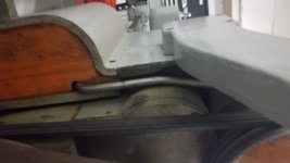
You will need to take the cover off the lathe on the motor end to see if the motor is turning without the pulley turning.
 
You will need to take the cover off the lathe on the motor end to see if the motor is turning without the pulley turning.

The motor was not turning. Seems like it's being told to stay in place (almost like it's being braked to 0 rpm). I can move the motor pulley and belt by hand and it's smooth, although there's some squeaking.

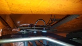
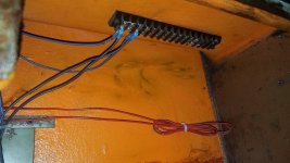
I think I traced the spindle lock wires, they appear to go to nowhere, but I'm not sure. The wires go into the casting into another compartment, and I see 2 red wires come out and go into some conduit looking stuff(only taken off the two covers on the motor end so far).

2018-04-08 14.02.41.jpg

2018-04-08 14.02.44.jpg

2018-04-08 14.03.39.jpg

2018-04-08 14.04.56.jpg
 
The motor was not turning. Seems like it's being told to stay in place (almost like it's being braked to 0 rpm).

Read That Fine Baldor DC Drive Manual. I have a .pdf copy if you do not, but other priorities.

FWIW - the Parker-SSD drives DO HAVE a "Zero Speed" state, both as a command and a "I HAVE IT NOW!" control OUTPUT signal. And a trimpot for it so it dasn't "creep".

And "creep"? Comical if not annoying.

If you want to WATCH a Dee Cee motor's slowest "creep" under control of one of these sophisticated 4Q drives? Bring rations for three days. They can go soo slow you will have to go for a s**t ELSE go blind observing just HOW slow.

Wall clock if not desk calendar for Revolutions-per...something other than minutes. Hours might work.

So, yes, you could very well be seing a commanded "hold position" situation.

Page Two:

Did your conversion utilize a tachogenerator or a shaft resolver?

That drive is capable of using at least one of those, if not either/both. If so optioned, (check manual and appropriate switches or jumpers on PCB) the goods need to "be there" and may have been stripped. Or even never "finalized" to begin with by whomever was doing the conversion.

Stay cheerful.

It looks more and more like a very good drive that was left in an odd option state, not a failed drive.
 
So, not really sure what changed... I opened up the electronics cabinet that houses the drive, to check for any errors. Drive turned on with power, detected lathe switch... went to move the spindle control lever... and apparently we have power... I have no idea what was different...

Oh, I think there's some interlocks on the doors... maybe one of those weren't closed all the way or something...

I appreciate you guys spending your Sunday evening with me!!!

Next on the list... making a 10-32 tap-slide hammer to remove a stubborn detent/piston for the d1-3 spindle nose... I bought replacements from MAC... but not having the detent is really annoying... although I don't imagine I'll really be removing the chuck often... if ever...
 
interlocks on the doors... maybe one of those weren't closed all the way or something...
Surely seems so!
Next on the list... making a 10-32 tap-slide hammer to remove a stubborn detent/piston for the d1-3 spindle nose... I bought replacements from MAC... but not having the detent is really annoying... although I don't imagine I'll really be removing the chuck often... if ever...

Are you sure?

ISTR there is a simple wire spring doing that "detent" job? And that NOBODY seems to sell them!

A "clock steel" kit from the usual suspects in that trade may sort it. Similar to a drill-rod assortment only far smaller diameters, and every bit as handy as shim stock kits.


Back
Top