beckley23
Titanium
- Joined
- Feb 19, 2003
- Location
- Louisville, KY, USA
In another topic in this forum, I mentioned that I had to rearrange the shop for a Series 60/61 16 X 78 lathe. The lathe is a little short of 13' long and about 4' deep and weighs approx 9200 LBS. I looked at the lathe approx 2-3 months ago, before it was listed on ebay, and had to decide if I could live without it, but most importantly, where to put it. While I was making my decision, I called my rigger to see if he could lift it, and he also quoted me a price, which was extremely reasonable. By the time I made my decision, the seller had listed it on ebay, it didn't sell, and then it went into his stores category. I contacted him a couple of times, and apparently he an offer, but the buyer didn't pick it up. One of my friend's is the seller's former employer, we all keep in contact and communicate and he told me the seller's bottom line, which was a tad bit more than I was thinking, but not unreasonable, and definitely not any where near the ebay price. I paid the bottom line, apparently I'm not the thief the seller thought I was.
Today was moving in day. Last Saturday the re-arrangement began. 2 surface grinders were relocated to the front of the shop, and several other pieces were shoved here and there, really making the shop barely usuable for a week. Fortunately it was light workload this week.
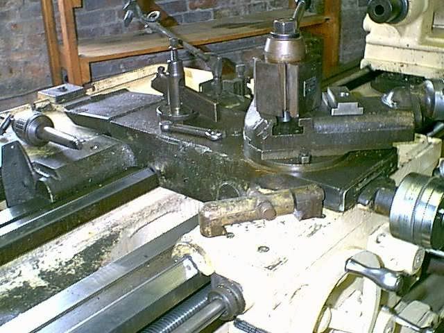
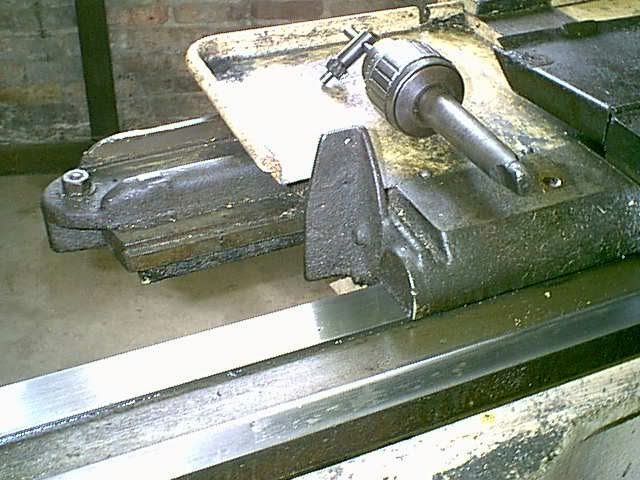
The tooling that came with the lathe; 15" 4 jaw, 12" 3 jaw, original 17" faceplate, steady rest, and a #18 Jacobs drill chuck, misc. wrenches. I have purchased on ebay a Dorian CA toolpost, and a CA 1-1/4" boring bar holder, and I'll make several other toolholders, but use the ones from the CY in the meantime.
Yesterday I finished learing a path to the lathe's new home, mainly moving the automatic bandsaw teporarily to the front of the shop where I normally park the 5000 LB Cat forklift.
The seller delivered the lathe this morning, and the rigger had it in place 45 minutes later, most of the time fine tuning the location. He spotted the lathe at approx 60* to the inal location, his forklift was too long to make the cut in the tight confines. He used my forklift to lift the lathe, via a webbed strap through the bed webbing on the tailstock end to spin the lathe to its final orientation. Then he used his forklift to pull the lathe about 2-1/2 feet closer to the front of the shop. No pictures of this part were taken, as I was otherwise occupied.
Pictures.
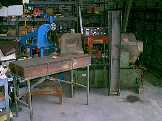
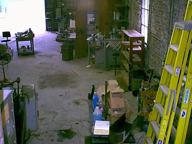
View of the shop from the office. A path was cleared from the overhead door, it's 14' X 14', to the rear of the shop. The oil spot, left of center, is approx where the headstock will be. There are paint lines at the upper right corner of the oil spot, and to the upper right corner of the UPS shipping table, for the tailstock end. The electrical cabinet for the #3 W&S is in the lower left corner, and the bar feeder has been removed(which is a story in itself).
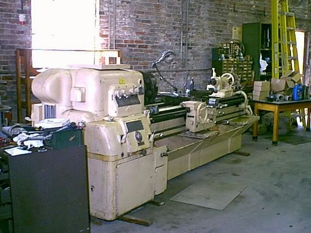
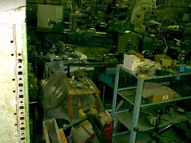
All the stuff in the shop had to go somewhere. Believe or not there are 2 turret lathes in there-somewhere.
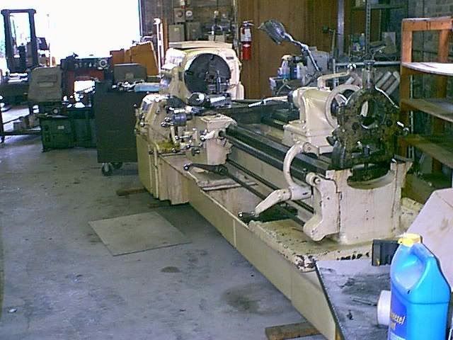
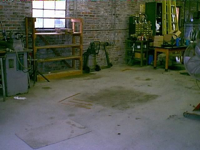
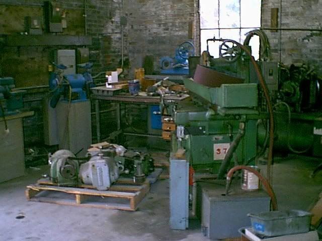
A better view of where the lathe is going. In this spot there 3 grinders, a 10 X 20 Landis Universal, accounts for the oil spot,and surface grinders, a Hardinge DV 59 and a couple shop tables. The Hardinge was several feet to the right of the window.
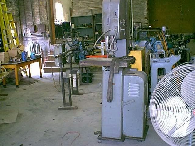
The surface grinders have been relocated to the front SW corner of the shop. This was the original location for the blue Norton when I moved here 16 years ago. The green #5 B&S was added later.
More pictures in the next post.
Harry
Today was moving in day. Last Saturday the re-arrangement began. 2 surface grinders were relocated to the front of the shop, and several other pieces were shoved here and there, really making the shop barely usuable for a week. Fortunately it was light workload this week.
The tooling that came with the lathe; 15" 4 jaw, 12" 3 jaw, original 17" faceplate, steady rest, and a #18 Jacobs drill chuck, misc. wrenches. I have purchased on ebay a Dorian CA toolpost, and a CA 1-1/4" boring bar holder, and I'll make several other toolholders, but use the ones from the CY in the meantime.
Yesterday I finished learing a path to the lathe's new home, mainly moving the automatic bandsaw teporarily to the front of the shop where I normally park the 5000 LB Cat forklift.
The seller delivered the lathe this morning, and the rigger had it in place 45 minutes later, most of the time fine tuning the location. He spotted the lathe at approx 60* to the inal location, his forklift was too long to make the cut in the tight confines. He used my forklift to lift the lathe, via a webbed strap through the bed webbing on the tailstock end to spin the lathe to its final orientation. Then he used his forklift to pull the lathe about 2-1/2 feet closer to the front of the shop. No pictures of this part were taken, as I was otherwise occupied.
Pictures.
View of the shop from the office. A path was cleared from the overhead door, it's 14' X 14', to the rear of the shop. The oil spot, left of center, is approx where the headstock will be. There are paint lines at the upper right corner of the oil spot, and to the upper right corner of the UPS shipping table, for the tailstock end. The electrical cabinet for the #3 W&S is in the lower left corner, and the bar feeder has been removed(which is a story in itself).
All the stuff in the shop had to go somewhere. Believe or not there are 2 turret lathes in there-somewhere.
A better view of where the lathe is going. In this spot there 3 grinders, a 10 X 20 Landis Universal, accounts for the oil spot,and surface grinders, a Hardinge DV 59 and a couple shop tables. The Hardinge was several feet to the right of the window.
The surface grinders have been relocated to the front SW corner of the shop. This was the original location for the blue Norton when I moved here 16 years ago. The green #5 B&S was added later.
More pictures in the next post.
Harry