Flail
Cast Iron
- Joined
- Oct 29, 2013
- Location
- Bonsall, CA
After recently acquiring a 1953 Monarch 10ee with a motor-generator I've been reading all the threads pro and con about preserving the M-G, using a phase convertor, using a DC drive or putting in a vfd and 3 phase AC motor. I then found the thread about http://www.practicalmachinist.com/vb/monarch-lathes/single-phase-power-motor-generator-10ees-153348/.
I thought this makes sense. It will cost about $40.00 in materials, allows the motor at anytime to be a nine wire or a 12 wire and doesn't degrade it's value to a purist, will save on the cost of a vfd or an RPC and the extra inefficiencies and complexities they would introduce to the system.
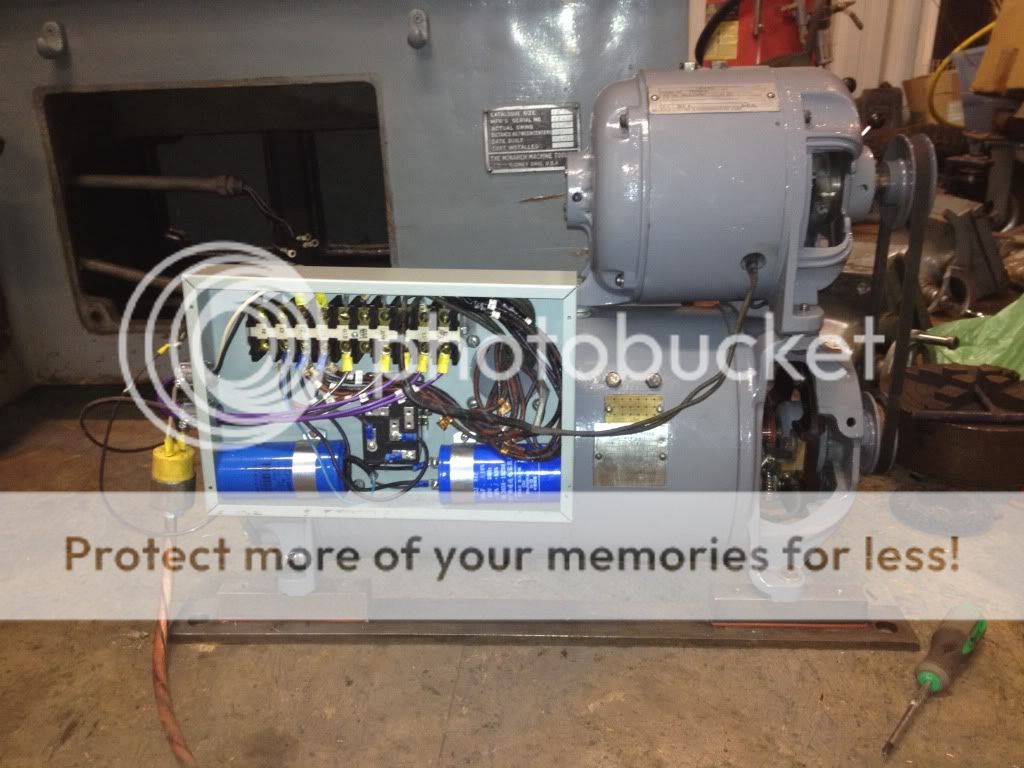
This thread details the practical steps to convert the 3 phase motor (of the motor-generator unit) to run on single phase. Basically it involves converting the Monarch 9 wire motor to a 12 wire motor. The problem is those 3 additional wires are buried deep within the motor buried under 60 year old grime and brittle varnish. Unfortunately the thread ends and doesn't progress to the point of opening up the M-G to do the conversion. Having more moxy than brains today I pressed forward and decided to look for the inner star point on the three phase motor. The M-G took maybe 30 minutes to wrestle out of the machine. All the wires have little metal tags to have identify them. In the first photo you can see the motor connector enclosure.

The lower three connector are T1, T2, and T3 which contain pairs of wires to wire this in the 230 volt mode. T1 pairs 1&7, T2 pairs 2&8, T3 pairs 3&9. You can see the external star point as the bundle of wires held together with the nut and screw in bottom of photo. Wires 4,5,6 form this external star point.
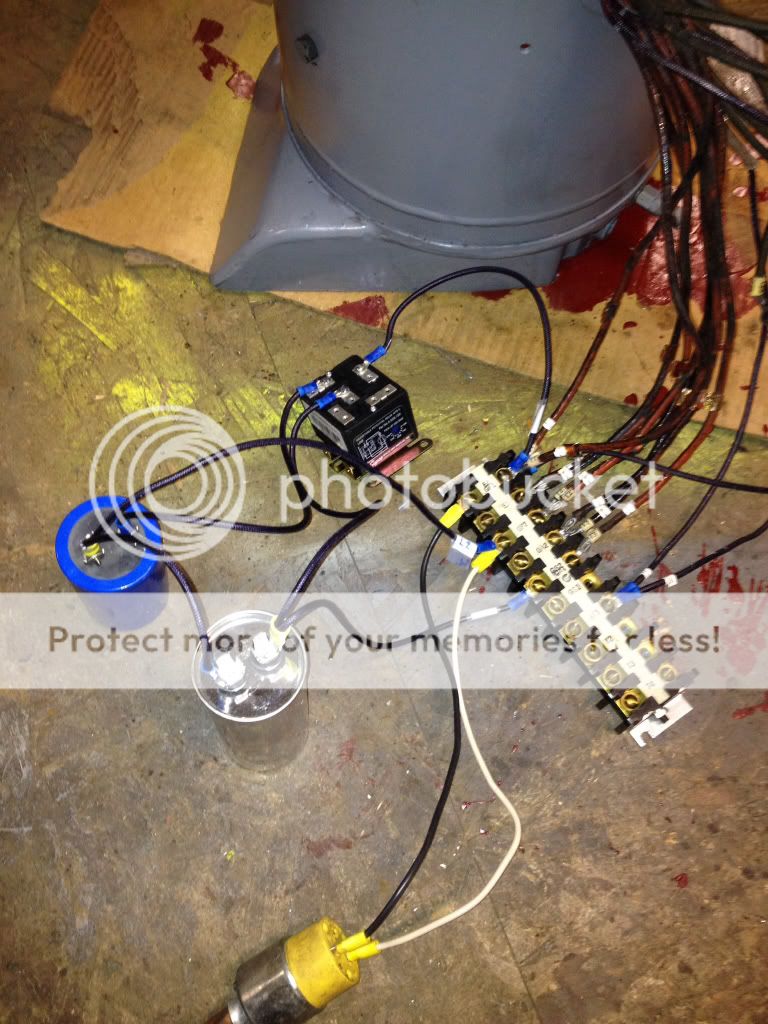
Photo 2 shows the wiring plate for the 230 volt and 460 wiring connections.
[
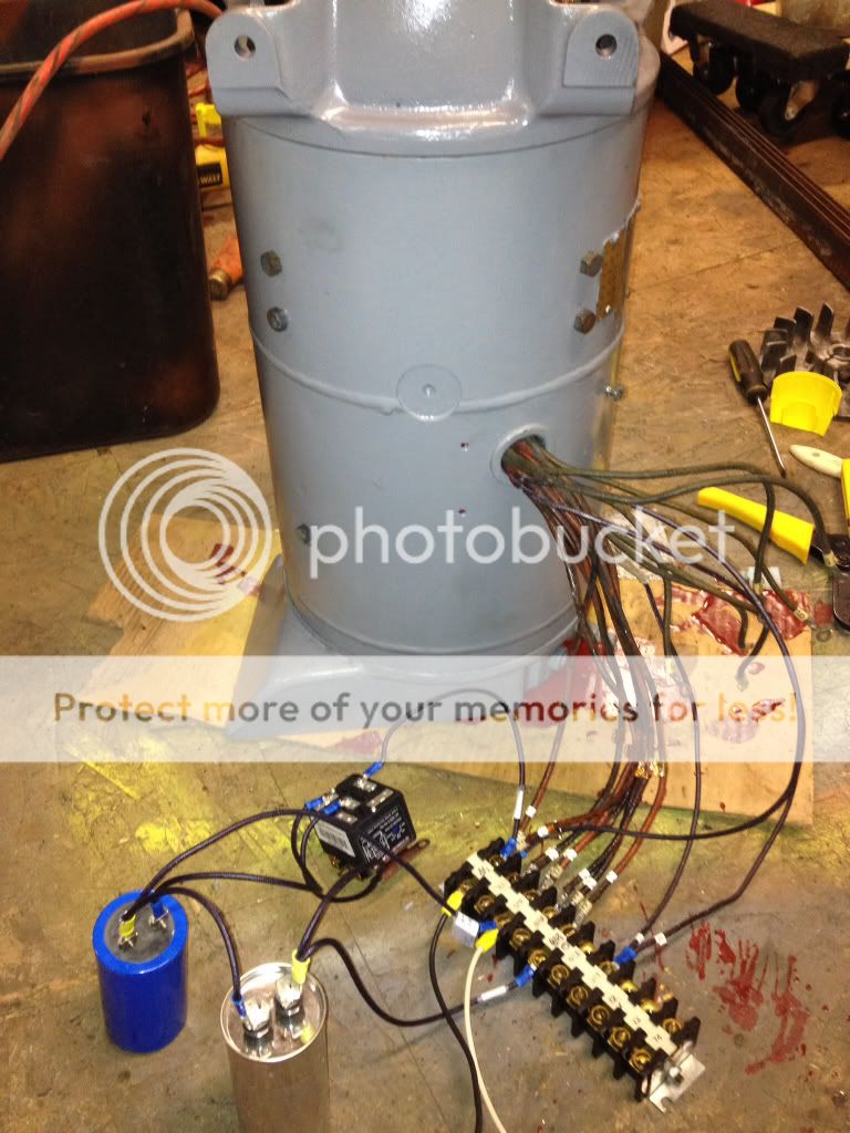
You will need to pull the M-G apart to get at the AC field. First take the connector enclosure off. Then cut the tape that binds all the wires together on the outside of M-G. Pull off the fan cover. The fan is held on by 2 Allen screws that can be felt between the fan fins. Each bell end has #4 3/8" bolts and you'll need to take out the bearing retainer bolts as well. Disconnect the generator brush wires which go back into the housing before pulling off from bell. Release the brush holders and pull the brushes out of the holders. The armature will then slide out. The area of the AC field you need to access is in the center of the case and it will be impossible to access this area with the field in the case. Remove the 8 bolts that hold the generator fields in and remove the DC fields. Keep track of the shims. The AC field is held from rotating by one external bolt. The field is held in the case by friction. You will need to press the field out of the case. To avoid bending the field laminations you will need to press it out. I built this fixture to do this:


Put this into the case so the fixture cups the field and presses against the laminations. Align the legs of the fixture with the 4 ridges in the motor case that retain the field. Don't press or hammer on the field wires or you will have a paper weight. Support the edges of the case with 4 long bolts that screw into the cover holes and press the field out.
I thought this makes sense. It will cost about $40.00 in materials, allows the motor at anytime to be a nine wire or a 12 wire and doesn't degrade it's value to a purist, will save on the cost of a vfd or an RPC and the extra inefficiencies and complexities they would introduce to the system.
This thread details the practical steps to convert the 3 phase motor (of the motor-generator unit) to run on single phase. Basically it involves converting the Monarch 9 wire motor to a 12 wire motor. The problem is those 3 additional wires are buried deep within the motor buried under 60 year old grime and brittle varnish. Unfortunately the thread ends and doesn't progress to the point of opening up the M-G to do the conversion. Having more moxy than brains today I pressed forward and decided to look for the inner star point on the three phase motor. The M-G took maybe 30 minutes to wrestle out of the machine. All the wires have little metal tags to have identify them. In the first photo you can see the motor connector enclosure.
The lower three connector are T1, T2, and T3 which contain pairs of wires to wire this in the 230 volt mode. T1 pairs 1&7, T2 pairs 2&8, T3 pairs 3&9. You can see the external star point as the bundle of wires held together with the nut and screw in bottom of photo. Wires 4,5,6 form this external star point.
Photo 2 shows the wiring plate for the 230 volt and 460 wiring connections.
[
You will need to pull the M-G apart to get at the AC field. First take the connector enclosure off. Then cut the tape that binds all the wires together on the outside of M-G. Pull off the fan cover. The fan is held on by 2 Allen screws that can be felt between the fan fins. Each bell end has #4 3/8" bolts and you'll need to take out the bearing retainer bolts as well. Disconnect the generator brush wires which go back into the housing before pulling off from bell. Release the brush holders and pull the brushes out of the holders. The armature will then slide out. The area of the AC field you need to access is in the center of the case and it will be impossible to access this area with the field in the case. Remove the 8 bolts that hold the generator fields in and remove the DC fields. Keep track of the shims. The AC field is held from rotating by one external bolt. The field is held in the case by friction. You will need to press the field out of the case. To avoid bending the field laminations you will need to press it out. I built this fixture to do this:
Put this into the case so the fixture cups the field and presses against the laminations. Align the legs of the fixture with the 4 ridges in the motor case that retain the field. Don't press or hammer on the field wires or you will have a paper weight. Support the edges of the case with 4 long bolts that screw into the cover holes and press the field out.
Last edited:


")