What's new
What's new

I/M Gearbox

beckley23

Titanium
Joined
Feb 19, 2003
Location
Louisville, KY, USA
A while back I got to thinking about the I/M gearbox and the fact that Monarch does it with 2 levers and no change gears. Let's face it, on the EE doing change gears has got to be a royal PITA, but the ability to flip 2 levers and do metric, that's the way to go. I was discussing this with Russ a few days ago, and he asked if I wanted some sheets of the I/M gearbox. He said they weren't to0 good, that they were not high resolution digitals. Send 'em and I'll see what I can do with them. A couple hours later I had them and was able to blow them up on my computerand see the details. I made some copies, 5 sheets, and took them to the blueprint shop and they were able to blow them up 300%, the lines are line fuzzy, but my "old" eyes were able to make things out. After a couple days of screwing around with the metric change gears calculations for my CK, I got around to the EE prints.
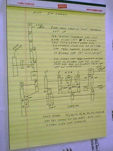
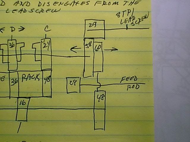
Here's my interpretation of the parts sheets. The calculations do check out.

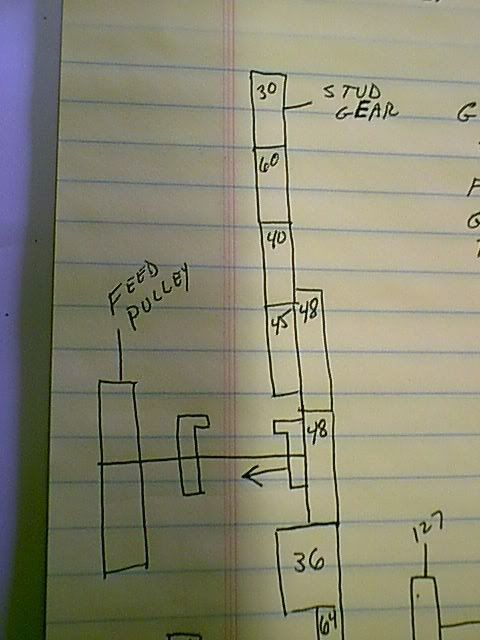
The gear train is shown in the inch mode.
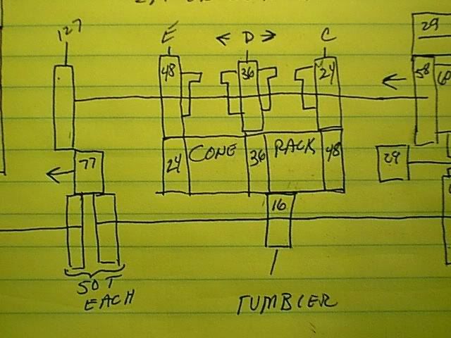
For metric threading the 77T gear slides to the left, that's the shifter on the left side of the gearbox, to engage the 127 and LH 50 T gears and disengage from the RH 50T gear. On the right hand side the 58/60 compound gear slides to the right to engage the 48 T with the 60T gear. This compound gear has 3 positions, to the left as shown it disengages the 29T gear on the leadscrew and engages the 29T gear on the feed rod, in the center it engages the 29T gear on the leadscrew and to the right has been previously described. This is the feed, inch, metric shifter on the right hand side of the gearbox.
The cone gears are 24, 26, 27, 28, 30, 36, 32, 40, 44, and 46. The 48T gear on the rack is the C position of the C-D-E shifter.
The gearbox itself is divided into 3 sections and I think they are pretty obvious. The center compartment contains the C-D-E and cone rack gears, the other 2 are on each side.
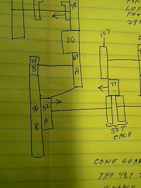
One of the problems in figureing out the gearbox on the parts sheets, and this is where the fuzziness of the exploded caused a bit of trouble is the 64A shiftgear and the 127 are on one shaft, or so it initially appears. They are separate rotations, it's just the 64 has an extension that goes into the 127, for support, I assume. Also the part sheet shows a shaft spacer on the left side preventing a shift. This spacer had to go, and so said a notation off to the side, at least that's the way I interpreted it.
There were a couple of other issues, mostly caused by the fuzziness of the exploded sheets, and I had to check the exploded views on the computer where the lines are much sharper.
There are at least 2 Pitch Diameters used in the gearbox. All the gears are 16DP, except the 24 & 96 A shift gears are 20DP, and I believe all the metric conversion gears are also 20DP.
Hope you can read my sketches, this is about as good as it gets with me.

im1.jpg


im2.jpg


im3.jpg


im4.jpg


im5.jpg


Harry
 
"I believe all the metric conversion gears are also 20DP"

They are all 32 DP.

45, 50, 55, 60, 65, 70, 75 and 80 T for the reverse shaft gear. 127 T for the gear which is compounded with the 60 T (16 DP) quadrant gear.

All gears are 14-1/2 PA, as far as I know.
 
Peter,
I'm describing the I/M gearbox, not the change gear conversion for the inch only machine, there's a big difference. 32DP would definitely be too small for the I/M gearbox. Until I or someone else can sit down and work out center distances and do the computations, we're not going to know. On the parts sheet, and these are scaled drawings, the 127 is larger OD than the 64T 16DP 4" PD, next to it.
Harry.
 
The I/M EE has been really nice for me because I need to cut metric threads at times.
The only other machine available is a L&S Powerturn with change gears, and its a nasty, oily. and time consuming chore to set up and then tear down.
One thing I noticed is, when the right hand lever is set from feed to inch and then metric, the shifting is not positive. That is,it seems the gears on the left side must be spring assited as the right lever can be in the metric possistion but it may not have shifted and the gears will rattle, or not shifted completly and they can pop out.
To get it shifted properly, I have to rotate the lead screw back and forth to make sure the gears are fully engaged.
Even with that, it takes less than 1 minute to switch from inch to metric.
 
I have to roll the spindle on my EE to do shifts effectively and get the gears engaged properly.
I didn't see any internal springs on the metric shifters. I think it's the nature of the beast.

I had to do some metric threads 4 weeks ago, my 2nd metric job in 18 years. A set of chasers, chargeable to the customer, for the die head took care of that problem, in about 15 minutes.
As you can tell I don't have much need for metric capability, but I not turning my nose up if an I/M machine is available at a steal.
Right now this is curiousosity for me.
Harry
 
"On the parts sheet, and these are scaled drawings, the 127 is larger OD than the 64T 16DP 4" PD, next to it."

127 T 20 DP would be 6.45" O.A. dia., 6.36" PCD.

64 T 16 DP would be 4.125" O.A. dia., 4.00" PCD.

I have a table of all available end/compound gears for the 10EE, for specialized pitches, and 16 through 32 DP are used, no doubt including 20 DP, and possibly others.

Naturally, Monarch wanted to make each gear as large as possible, consistent with fitting within the enclosed end gear unit.

My guess is the I/m 10EE cluster has 24, 26, 27, 28, 30, 36, 32, 40, 44 and 46 T, in that order, as that set produces all possible pitches, while being the smallest number of teeth in each position, without having any fractional teeth.

One row below 27 is 13-1/2, and two rows below 26, 30 and 46 are 6-1/2, 7-1/2 and 11-1/2, so that pretty much defines the low end of the box.

The sequence ... 30, 36, 32, 40 ... may seem anomalous, but the print of the cluster selector confirms that this jump is indeed there.

[ 07-27-2007, 10:09 AM: Message edited by: peterh5322 ]
 
Harry,

just as I had given up on figuring out the workings of the I/M box your work comes as a blessing.

I have started a post earlier asking about the internals of a I/M type box. I have an exploded view of the Colchester Student one but that has a very limited metric range and does not use a 127 gear so I figure that metric pitches were by approximation.'

Actually Peter and Donie and yourself were very helpful in answering all the questions I asked.

I am making the assumption that your drawings are 'not to scale'.

I have a 'few'questions that I would like to ask.

1. 45/48 input compound

Is this a true compound gear?
Is it required to get the correct 1:1 ratio on the 8 TPI?

2.Feed Pulley
Where is the drive for the feed pulley coming from and would you know the ratio?

3.A-B Selector

Are 96/32 ganged? I.E when shifting to A doe the 96 move with the 32?

4. C-D-E selector
What gears does it mesh with on the Cone Rack??
Which gears are fixed to the shaft and wich are not? Do the clucth with one another to form 'compound' gears?

5. Cone Rack / Tumbler gear.

I'm assuming that the 16T tumbler gear is moving on a 'fork' linked to a rack that is connected to the 1-10 selector. How does it do that when all gears on the cone rack have different OD's??

Are all cone gears keyed to the shaft?


Sorry for getting carried away here but I realy would like to design, adn build, an usable I/M boc for my humble Myford.

I know the range on the coarse threads is way beyond the Myfords capabilities but would figure out how to step down the range by changing the input gear.

As far as gear sizes are concerned, I believe I can reduce the gear OD's considerably by changing the DP or MOD's used. Would look a bit silly ending up with a box bigger than a lathe.

Thanking you in advance.

Piet
 
The input gear train 30-60-40-45 duplicates the Imperial gearbox, and allows the feeds to be the same. The Imperial thread leads, too.

60 and 40 are idlers, so the end gear (what Harry labeled as "Stud") to screw gear ratio is 30/45, or 2/3, just as it is in the Imperial box end gear unit.

I presume the 60 T quadrant gear is still there to allow use of the previously available optional quadrant and end gear sets, which allowed various special Imperial pitches to be achieved.

30-60-40-45 would, therefore, be 16 DP to keep the end gear unit size the same.

We already know the I/m box is the same size as the Imperial-only box, as the two are physically interchangeable.
 
The simple stuff first.
The basic layout of Monarch gearboxes, and most other gearboxes, can be determined by looking at the thread chart.
On Monarch's, there are 2 range shifts and these are 1) the A-B shifter, which on the EE A is 1, or each revolution of the spindle the last gear, in this case the 32A rotates 1 time, on my CK and CY the equivalent gear would rotate twice, when the B shift is selected the 96 T gear rotates 1/8 time per revolution of the spindle, on the CK and CY it is 1/4. Thus you can see that the ratio is 8:1. If you look at the AC and BC lines and compare them, you will see that A is 8 times B in any vertical selection for the corresponding C-D-E selection. The motion of the 96/32 shaft which has the 16T tumbler gear is transmitted to the cone rack and then to the C-D-E shaft. The C-D-E gears mesh with gears shown in the sketch above. The C and E gears are fixed in location of the shaft but are not keyed to the shaft, they are free spinning. The D gear, however is keyed to the shaft and when this postion is selected it is driven by the 36T gear on the cone rack. If the D gear is moved axially either right or left, it is out of engagement with all gears on the rack, but because it has clutch teeth on each side it will be engaged with either the 24T or the 48T gear. Thus the ratio of the C-D-E selection 2:1(48/24), 1:1(36/36), or 1:2(24/48). The motion is then transmitted to the 58T gear on the C-D-E shaft, which drives the 29T gear on the 8TPI leadscrew.
The are 10 thread selection gears on the cone rack, plus the 48T gear. These gears are 24, 26, 27, 28, 30, 36, 32, 40 44, and 46 teeth and these are the threads on the BC line of the chart. You will notice that the 36 and 32 teeth gears are not in sequence, and this is to make the C shift possible. It is also a way for Monarch to make space on the left and right sides to accommodate the metric selection gears, ie; the 50-77-127 on the left side and the 48-60 sequence on the right side. In the "Inch" gearbox the gears, 32 and 36, are in sequence, but there is a space between the 36 and 49 tooth gears on the cone rack that allows the C shift, and the metric gears are not present.
If you follow the drive transmission you will also see the drive for inch follows a different route than the metric route.

The drive for the feed pulley comes from the spindle via a flat belt.

The cone gears are keyed to the shaft.

All gears that are together, such as the 45/48, 96/32, 58/60 are compounded, and the 96/32 slide as one. Keep in mind the 96 is 20DP and the 32 is 16DP.

I left a gear out of the tumbler set-up. The 16T gear drives a 48T? which the selected cone rack gear. The 48T does not affect the calculations only the direction of rotation.

The 50, 77 and 127 teeth metric gears are 30DP. I did some measurements(rough) and calculations and confirmed them with Russ this evening, who has a much clearer scan now. The DP's and tooth counts, so far, are called out on the drawings, it's a matter of being able to see them. I still haven't figured out the 48 and 60 T gears on the right side, and it may be awhile till I get to it. A rush order came in today and that comes first.

Hope I have answered your questions, if not ask again.
Harry
 
Harry,

that was very informative, to say the least. Trying to get thru the maths and the dime is underway.

I still have a two 'mechanical' questions left.

1. Tumbler Selector

How does this work? I believe both the Cone and Tumbler Shaft positions are fixed. The Tumbler selector knob seems to rotate only so either the 16, or left out 48 Idler must shift over it's shaft across the cone stopping at the selected gear. Since all cone gear have different OD's how would the Tumbler or Idler engage between the Cone gears and out-put shaft?

It looks like the box does not have the traditional tumbler pattern that slides sideways and up as smaller cone gears are selected.

2. RH Selector

Is the 58/60 compound just a slide gear that either meshes with the 29 Feed Gear, the 29 Inch Gear and finally engages 48-60/58-29 in Metric position, therefor acting as an additional transposing gear??

Thanks,


Piet
 
In the EE, the 16T tumbler is actually a long shaft with gear teeth, the is a bracket that carries the 48T idler that slides on the 16 T gear. Technically the bracket is the tumbler. The bracket has a spherical cam follower machined, or mounted, on the other end. The cam follower is guided by a flat cam plate assembly that is mounted in the top of the gearbox. the cam plate is moveable, via rack and pinion gear(s), the pinion being attached the handle on the upper right hand side of the gearbox. When the handle is down the 48T gear is out of engagement with the cone rack, when up it is in engagement.
You are correct in the assumption that the 16T "tumbler" gear and the cone rack gears have fixed positions.
The 58/60 compound gear has 3 positions, left is feeds, center is inch threads and right is metric threads. The 48-60T gears are the other end of the metric conversion. The 58T gear is always driving a 29T gear, either on the feed rod or the leadscrew.
When you do the math, the 77T gear should be treated as an idler, as is the 48T gear in the tumbler bracket. It's not going to affect the calculations. These gears may not affect the numbers, but their use is crucial to the proper operation of the gearbox.
Harry
 
Harry,

thanks again for that information.

I assume that the 48 'Idler' and bracket slide on a dedicated shaft. The shift pattern itself is than hidden in the box and released by the RH lever on the upper side if the box. I thought that was some kind of reverse or dog clutch lever for the leadscrew.

I think this cam and camplate etc., although cool and looking clean, could be too complicated to copy / design. Can you see any reason why a traditional slide/hole pattern would not work??

Thanks,

Piet
 
If you look at the sketch I drew, the 16T "tumbler" gear shaft is a very long shaft. The 16 teeth are cut in the section that is in line with the cone rack of gears. The shaft extends beyond internal walls in the gearbox casting, and is supported by ball bearings mounted in the casting. The RH 50T metric gear is mounted on the left end and the 48T metric gear is mounted on the right end The 48T tumbler bracket slides on the section with the 16 teeth.
The thread selection can not be changed, as far as I know, with the right hand lever in the "up" or engaged position. On a few occassions I've tried, but I didn't force the issue.
There is no reason that you couldn't design an open type of gearbox.
The cam plate takes the place of the "traditional" slide hole pattern on the front of the gearbox, and allows the gearbox to be a closed system with an oil splash lubrication.
There is another topic in the Monarch section about metric threading started by Roberto, Daryl Bane has posted pictures of his "inch" gearbox, you may want to take a look at it.
Harry
 
Peter has referred to the quadrant in an earlier post and the use of change gears. I think this is a definite possibility, as the metric offering on the I/M chart is limited. You get, IMO, the most commonly used metric threads, but there are several that are not available. I feel that the "secret" in the available selection is the 48-60 reduction in the final output.
On the same course, I looked at a Series 613 with an I/M gearbox, last fall, and there are 99 each of inch and metric threads. The similarties between the 2 gearboxes are not surprising, they are both, externally, laid out the same, however there there is a notable difference. The A-B, and C-D-E selection has been changed to A-B-C and D-E-F, with 11 thread gears on the cone gear rack on the 613. I didn't study the charts very closely, but I did notice some very strange "inch" threads that could only correspond to an expansion of the EE I/M set-up to include some more useable metric threads, and I assume in the finer pitches, as the EE layout seems to do quite well in the coarse pitches.
Comments, theories?
Harry
 
Harry,

thanks for pointing our to Daryl's pictures. Although it does not show the complete inner workings I'm geting the picture.

So the RH selector unlocks the camplate allowing the 48 to move accross the cone gears. As soon as the proper gear is selected, lifting up on the RH lever will engage the cone gear and 16T tumbler.

That 613 Series I/M sounds very interesting as well because of it wide range. I thought the 613 was a much larger adn coarser lathe than the 10EE.

Would be nice to know 'how they did it'

Now it will all come down to proper sizing. What would be the minimum DP or MOD to use and still end up with a sturdy enaough box that won't spit it teeth as soon as it has to do some work.

Does Monarch use Case Hardened gears??

I used to own a SB-9A and did a complete overhaul on the lathe including the box and found that the gears were un-hardened, I believe, as I dropped one on the floor and a tooth got dinged and could file it back into shape. This was one of the cone gears, I am not sure about the change gears.

Regards,

Piet
 
The 613 I looked at, was a 2013 X 108, 20" over the bed, 13" over the carriage, 108" btwn centers, 15 HP, and weighed 10,000 LBS approx.
The EE has finer feed rates available, mainly because it is more suited for smaller work. You have to consider the EE was designed and built for a different class of work.
Monarch lathes, with a couple of exceptions, were not to built to a cost, but rather with quality in mind. As far as I know all, the gears in Monarchs are made from alloy steels and properly heat treated. South Bends were built to a cost.

I can't be of much help on your design, but about 30 years ago I built a QC gearbox for an Atlas 6" lathe, which is comparable in size to the Myford, and used either 20, 24 or 32 DP gears in the gear box.
Harry
 
Harry,

Thanks again for your prompt response.


Won't bother you again, for a while at least :D

I think I will do some maths and a drawing and probably, hopefully, be ordering semi-finished gears from HPC in the UK as I can not find a local source that does them off the shelf.

Although it could be a valuable exercise to learn to cut gears, although there are a lot of them.

P.S. Hats off for having gone thru the exercise a 'little' earlier.


Kind regards,


Piet


Back
Top